Team:Aachen/Notebook/Engineering/WatsOn
From 2014.igem.org
(→GUI(graphical user interface)) |
|||
| Line 48: | Line 48: | ||
{{Team:Aachen/BlockSeparator}} | {{Team:Aachen/BlockSeparator}} | ||
| + | |||
| + | = Hardware = | ||
| + | <span class="anchor" id="watsonhardware"></span> | ||
| + | |||
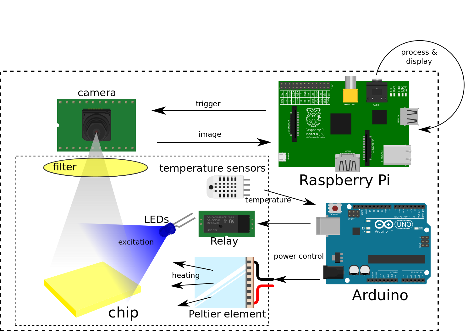
| + | {{Team:Aachen/Figure|Aachen_Device_Hardware_Graphics.png|title=Hardware components||width=750px}} | ||
| + | |||
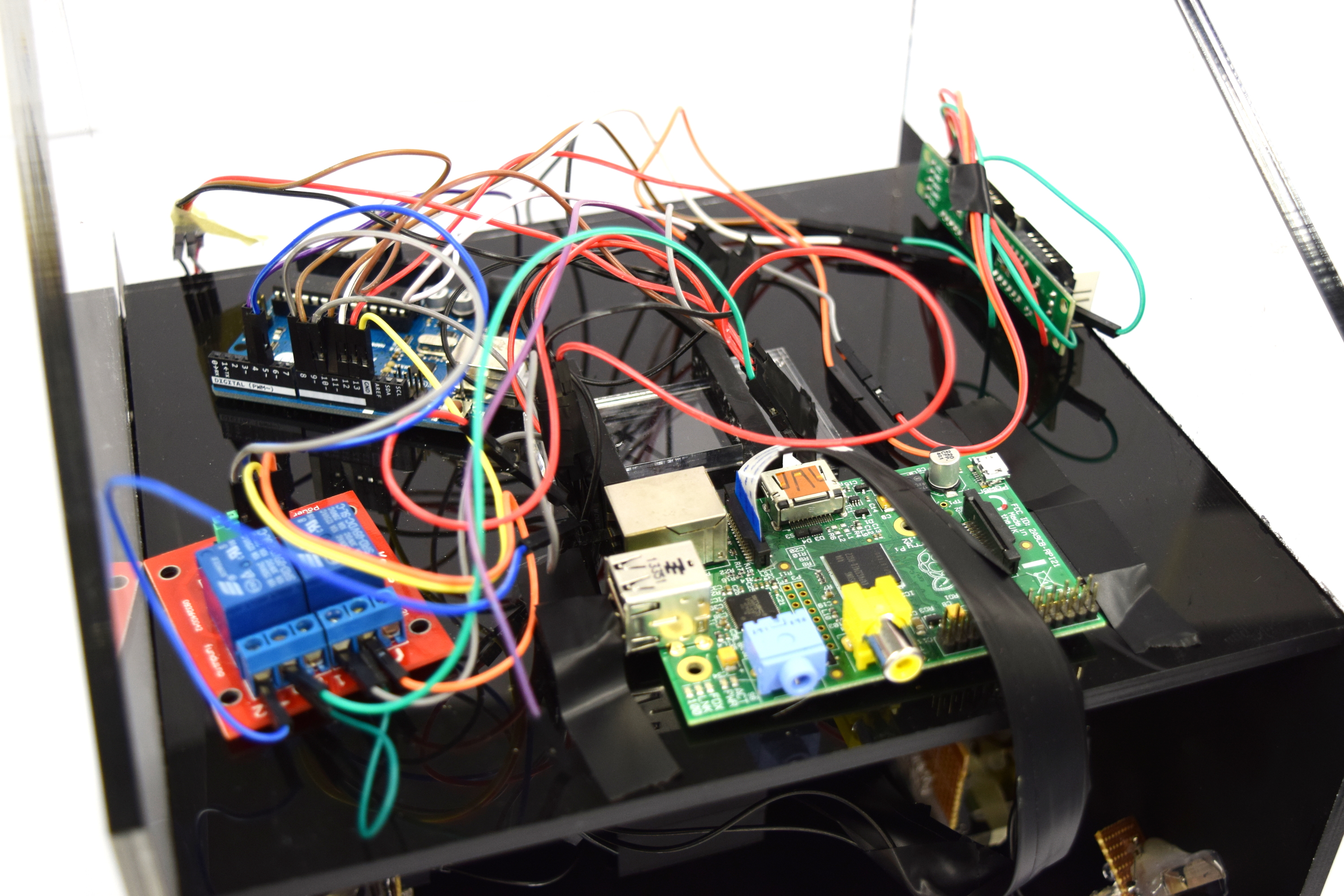
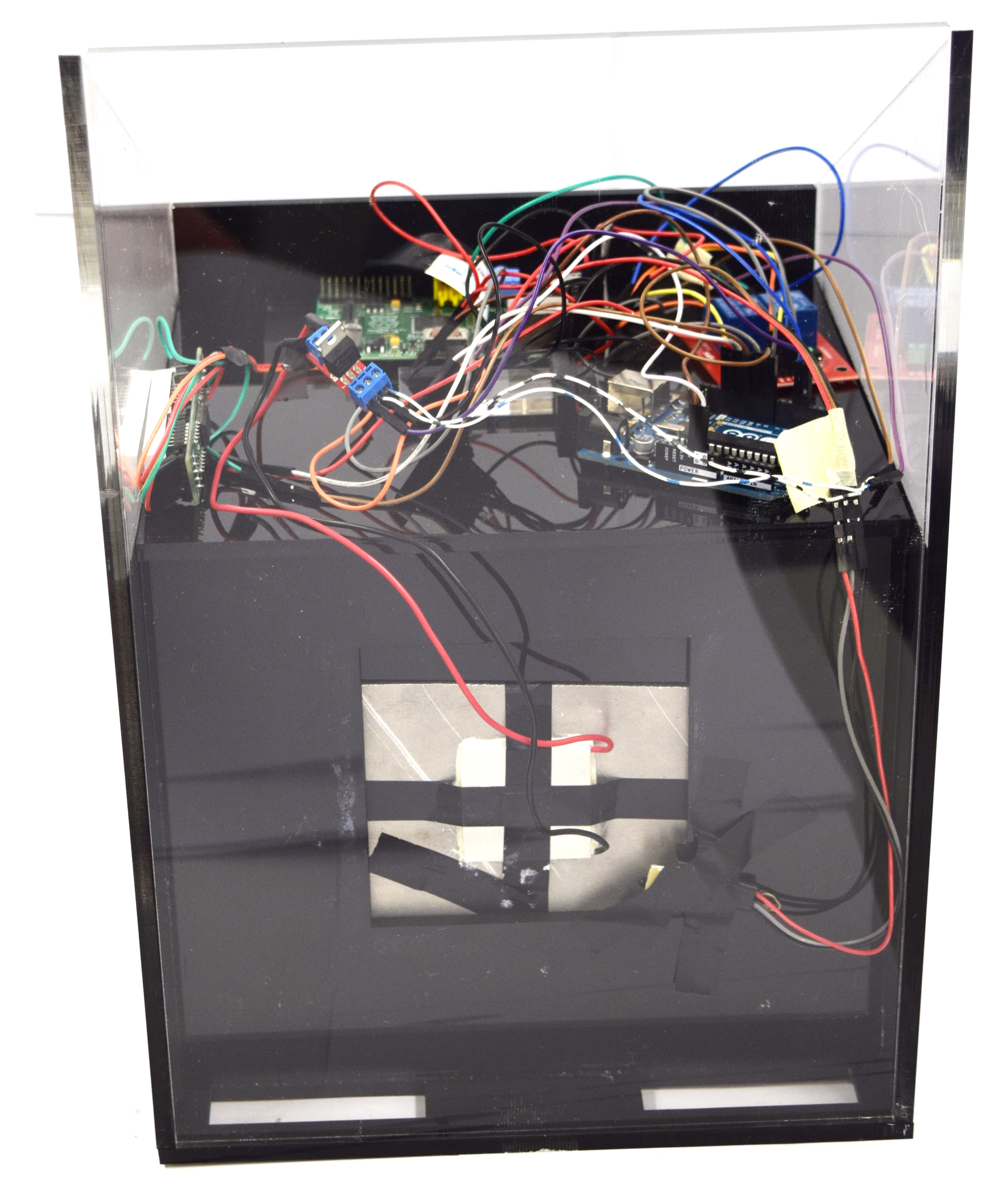
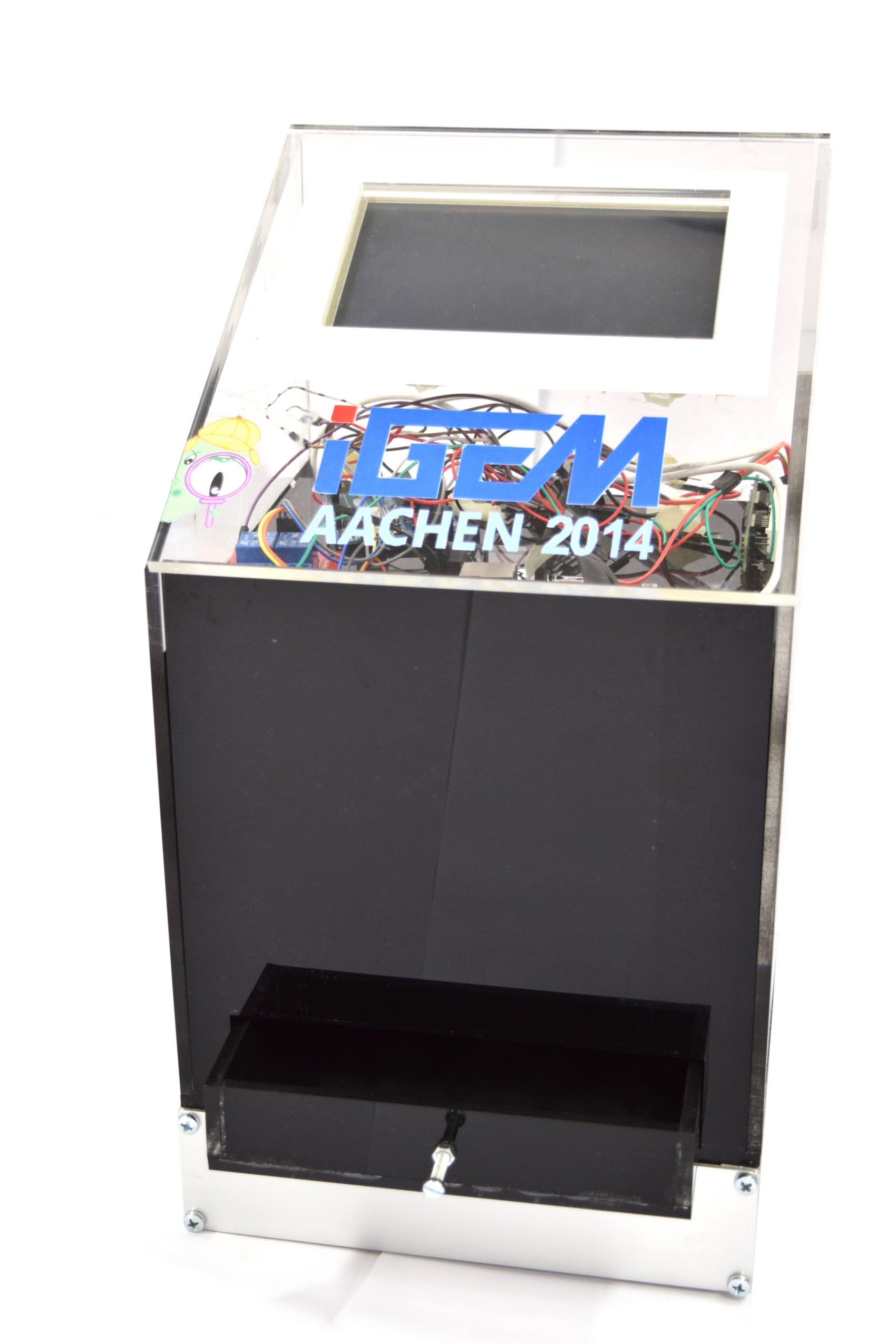
| + | * '''Raspberry Pi''' : The Raspberry Pi is a small single-board computer which runs a Linux operating system from an inserted SD-card. The steps which are required to setup a fully working system are described here[https://2014.igem.org/Team:Aachen/Notebook/Engineering/WatsOn#pisetup]. The main purpose of the Raspberry Pi is to run the software described above, control the attached camera and to show the GUI on the display. The big advantage of this board is that it is very powerful, cheap and therefore perfectly fits our needs. | ||
| + | |||
| + | * '''Raspberry Pi camera''': The camera is directly connected to the Raspberry Pi board and takes the images of the chips. | ||
| + | |||
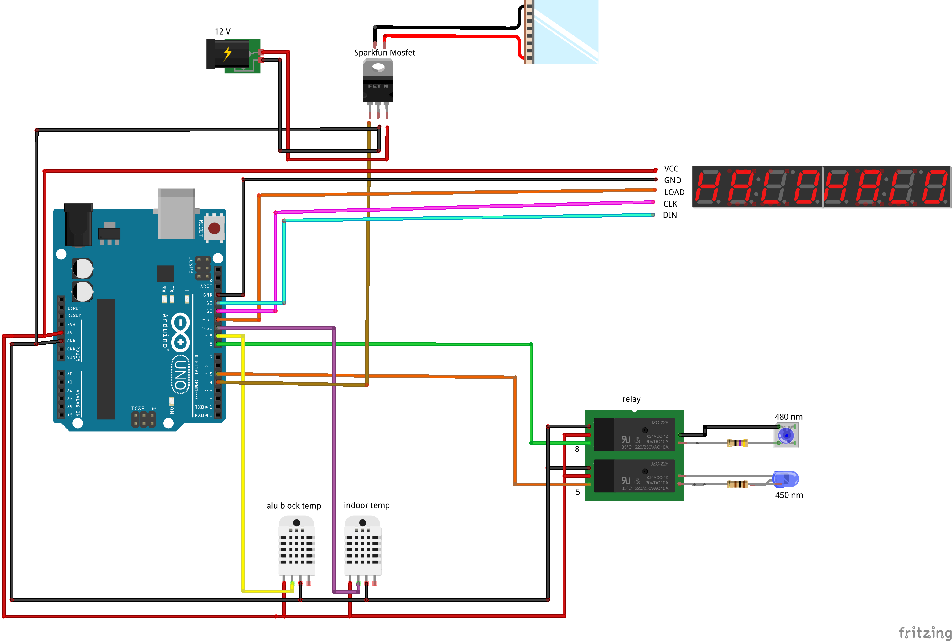
| + | * '''Arduino''': The arduino board sets the power and thus controls the temperature of the Peltier heater. The power is set by evaluating the received values from the temperature sensors for the interior of the device and the aluminium block. Additionally the arduino receives commands from the Raspberry Pi to turn the excitation LEDs on and off. | ||
| + | |||
| + | * '''Relay''': The 2-channel relay works like two light switches which either are turned on or off. They control the 450nm and 480nm LEDs. The channels are connected and turned on and off by the arduino board. | ||
| + | |||
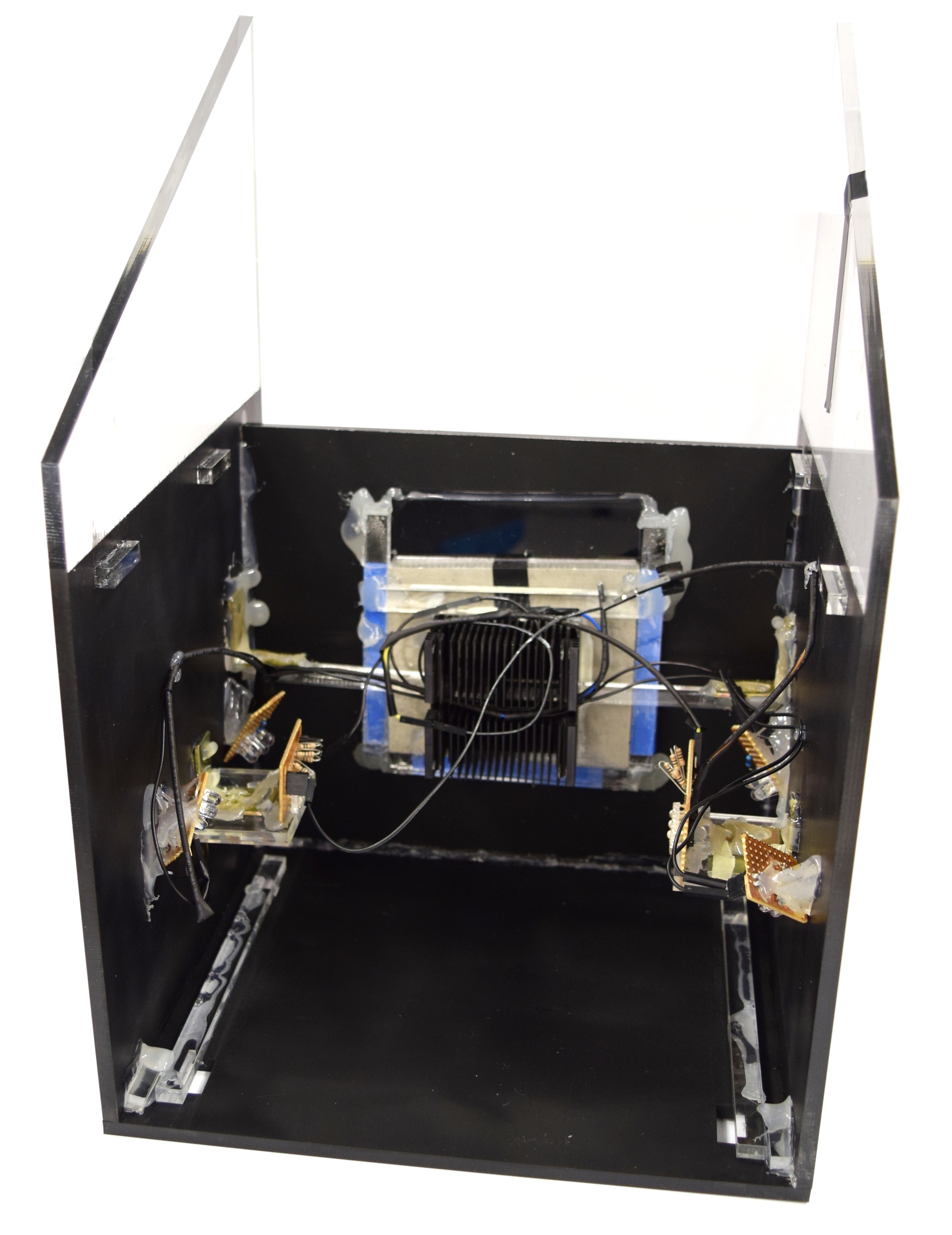
| + | * '''Peltier element''': A Peltier component transforms an applied power into a temperature gradient which leads to a hot surface on one side of the element and a cooler one on the other. The Peltier element connected to the aluminium block heats up the interior of the device to incubate the sensing cells at 37°C. | ||
| + | |||
| + | * '''USB WiFi stick''': The USB WiFi stick connects the Raspberry Pi to a local network. | ||
| + | |||
| + | * '''Display''': The 8-digit display is connected to the arduino board and shows the current interior temperature | ||
| + | |||
| + | {{Team:Aachen/FigureFloatRight|Aachen_Filter_010.png|title=010|subtitle=|width=70px}} | ||
| + | {{Team:Aachen/FigureFloatRight|Aachen_Filter_505.png|title=505|subtitle=|width=70px}} | ||
| + | |||
| + | * '''Filter slides''': To block the light that is emitted from the LEDs a filter slide is placed in front of the camera. This step is taken to get a clear fluorescence signal from the chips. The characteristic of the filter slide is selected depending on the frequency of the LEDs which are either 450nm or 480nm ones. We used '505 Sally Green' for the 450nm and '010 Medium Yellow' for the 480nm LEDs. | ||
| + | |||
| + | {{Team:Aachen/BlockSeparator}} | ||
| + | |||
= Software = | = Software = | ||
| Line 82: | Line 109: | ||
{{Team:Aachen/BlockSeparator}} | {{Team:Aachen/BlockSeparator}} | ||
| - | |||
| - | |||
| - | |||
| - | |||
| - | |||
| - | |||
| - | |||
| - | |||
| - | |||
| - | |||
| - | |||
| - | |||
| - | |||
| - | |||
| - | |||
| - | |||
| - | |||
| - | |||
| - | |||
| - | |||
| - | |||
| - | |||
| - | |||
| - | |||
| - | |||
| - | |||
| - | |||
[[File:Aachen_14-10-15_DIY_Cellocks_iNB.png|right|150px]] | [[File:Aachen_14-10-15_DIY_Cellocks_iNB.png|right|150px]] | ||
Revision as of 20:16, 16 October 2014
|
|
|
|
|
 "
"


![350px] [File:Aachen_Device_.3jpg](/wiki/images/7/7b/Aachen_Device_2_3.jpg)
