Team:Aachen/Notebook/Engineering/ODF
From 2014.igem.org
(→Construction Steps) |
(→Combined Device) |
||
| Line 338: | Line 338: | ||
{{Team:Aachen/Figure|Aachen_ODF_combined_Steckplatine.png|align=center|title=Our novel biosensor approach|subtitle=Expression of the TEV protease is induced by HSL. The protease cleaves the GFP-REACh fusion protein to elecit a fluorescence response.|width=900px}} | {{Team:Aachen/Figure|Aachen_ODF_combined_Steckplatine.png|align=center|title=Our novel biosensor approach|subtitle=Expression of the TEV protease is induced by HSL. The protease cleaves the GFP-REACh fusion protein to elecit a fluorescence response.|width=900px}} | ||
| + | == Construction Steps == | ||
| + | {| class="wikitable centered" | ||
| + | |- | ||
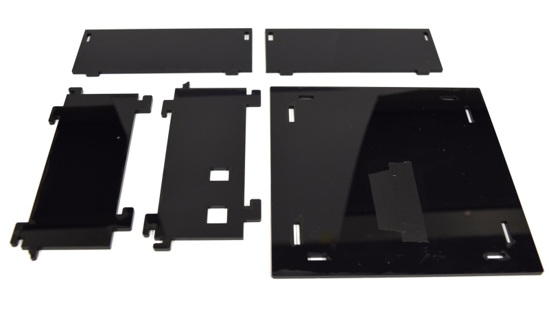
| + | | [[File:Aachen_ODF_9.JPG|300px]] || First we want to assemble the casing. Once you have all the cut parts, you can start to assemble them. For cutting, we really recommend using a laser cutter. | ||
| + | |- | ||
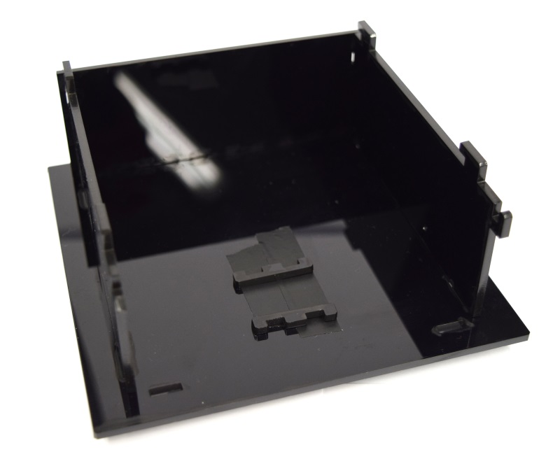
| + | | [[File:Aachen_ODF_8.JPG|300px]] || Attach the cuvette-holder holders such that the cuvette holder is placed directly under the opening hole. | ||
| + | |- | ||
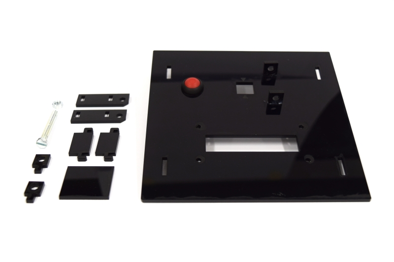
| + | | [[File:Aachen_ODF_4.JPG|300px]] || Next build the lid of the device. At this stage you can already mount the button. We recommend to glue any parts. | ||
| + | |- | ||
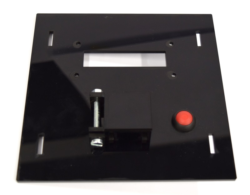
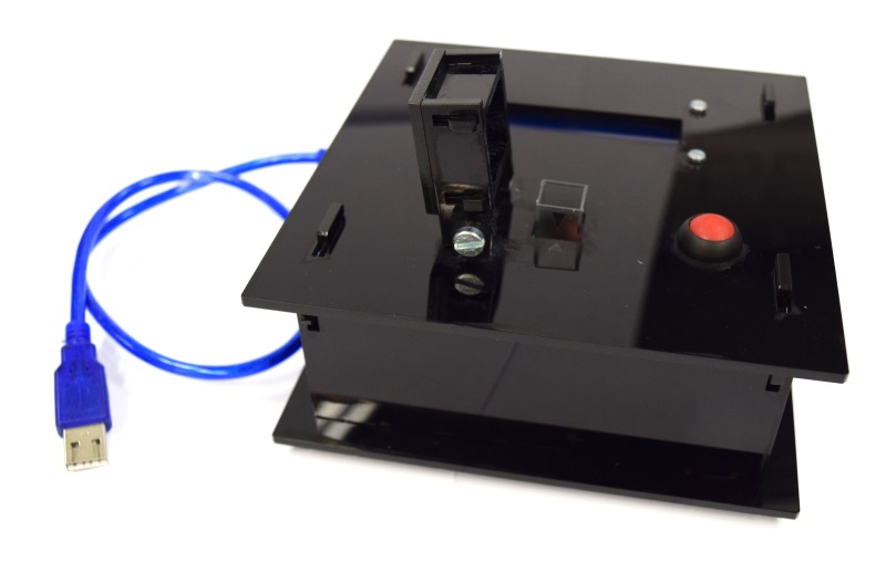
| + | | [[File:Aachen_ODF_3.JPG|300px]] || Your lid finally should look like this. | ||
| + | |- | ||
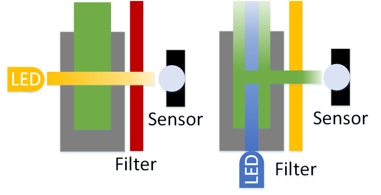
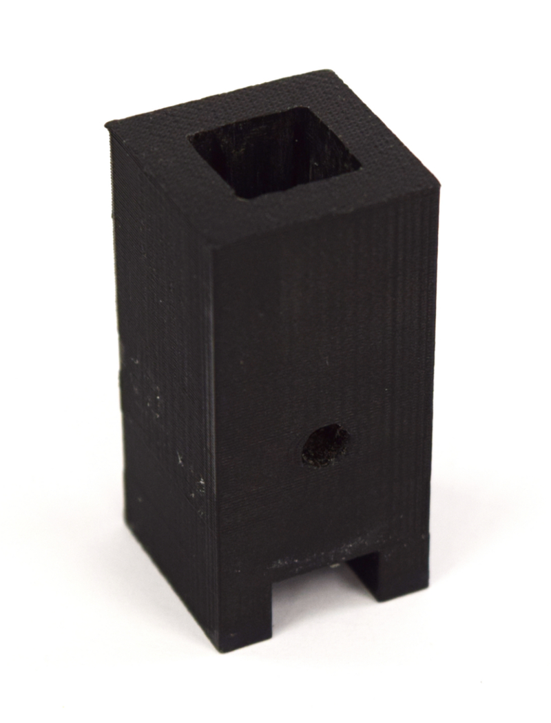
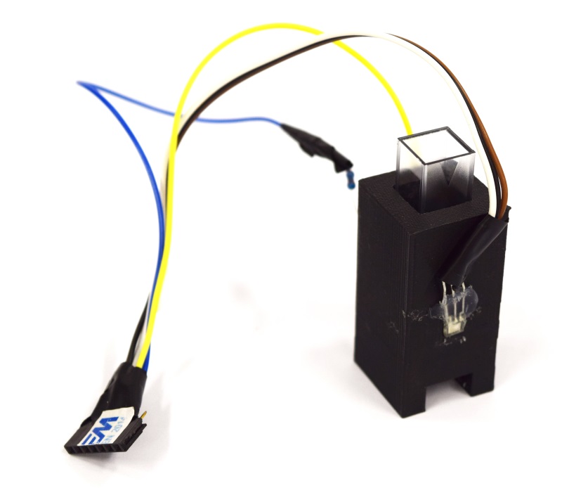
| + | | [[File:Aachen_ODF_11.JPG|150px]][[File:Aachen_ODF_10.JPG|150px]] || Next we want to assemble the cuvette holders. On the side with the square hole attach the light-to-frequency sensor with glue. For the OD case place the orange LED opposite, or for fluorescence, the LED in the hole in the bottom. Make sure to close any remaining open hole! Please attach a piece of filter foil (approx. $7 \times 7 mm^2$) from the inside in front of the light to frequency converter. Forceps is highly recommended. | ||
| + | |- | ||
| + | | [[File:Aachen_ODF_12.JPG|300px]] || Your final assembly should then look like this. Now place the correct filter into the cuvette holder, directly in front of the sensor. Make sure that the filter does not degrade due to the glue! | ||
| + | |- | ||
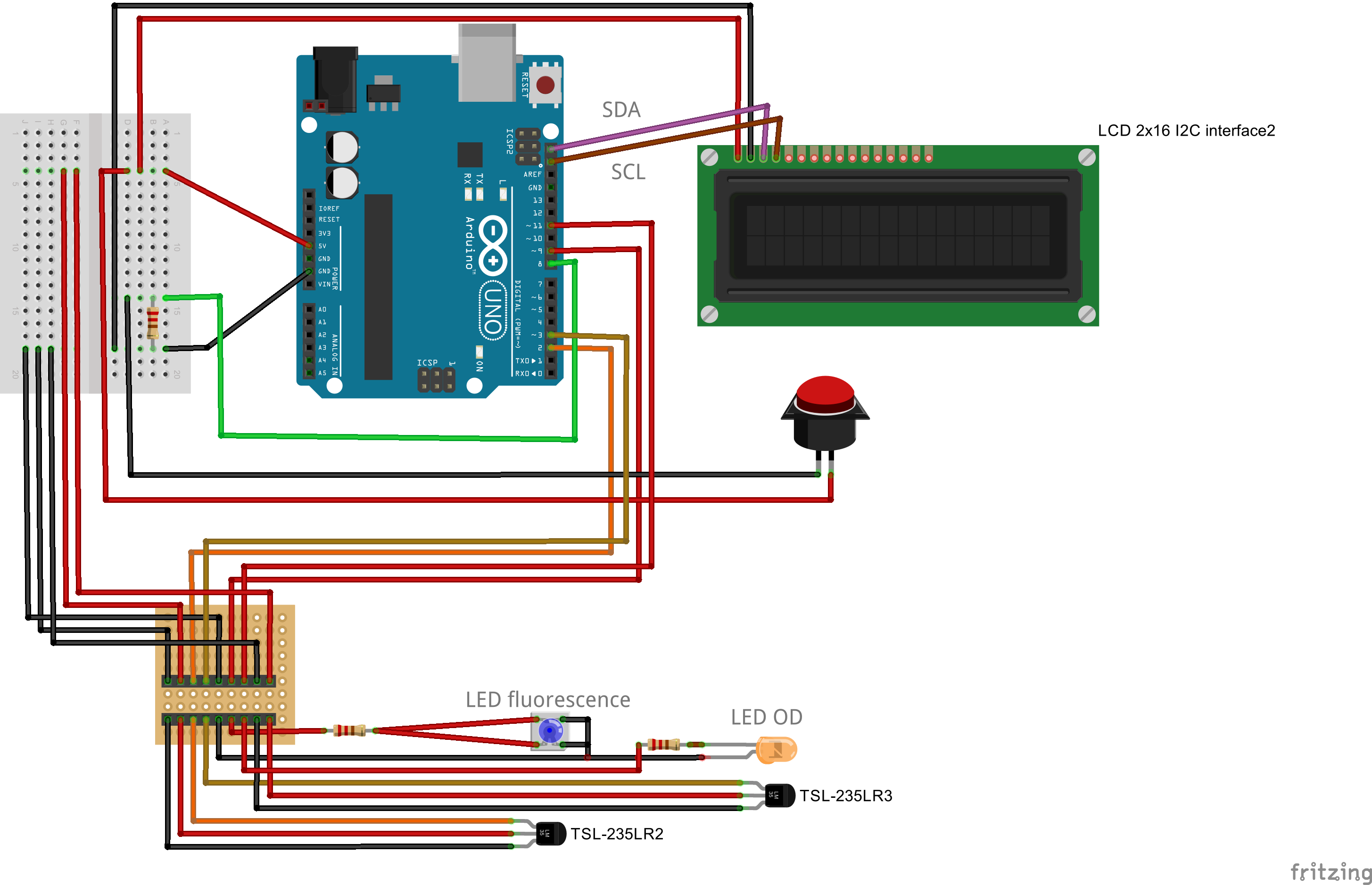
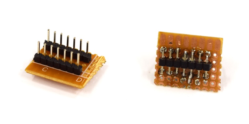
| + | | [[File:Aachen_ODF_14.JPG|300px]] || As the case can be used for both, fluorescence and OD measurement, we use a combined plug. Just three header rows (7 pins) and connect them as we did. | ||
| + | |- | ||
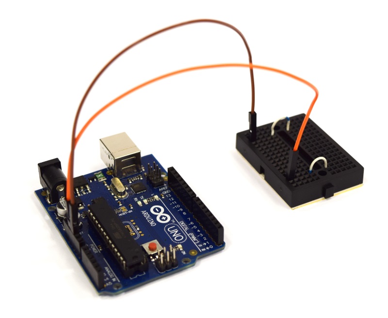
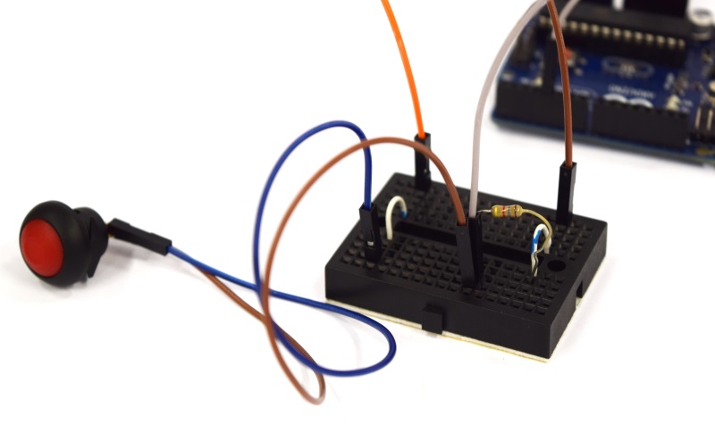
| + | | [[File:Aachen_ODF_1.JPG|300px]] || Now we're doing the wiring. Connect the Arduino 5V and GND such that you have one 5V and one GND line on your breadboard. | ||
| + | |- | ||
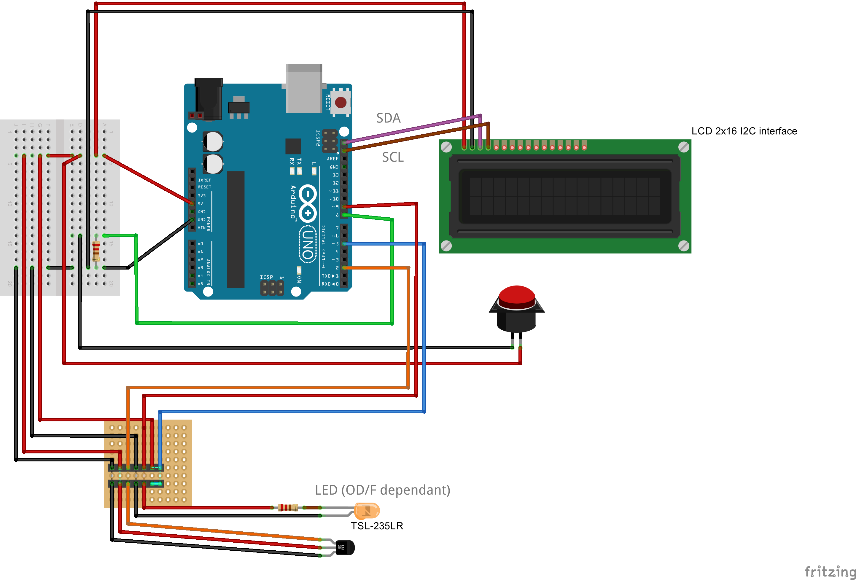
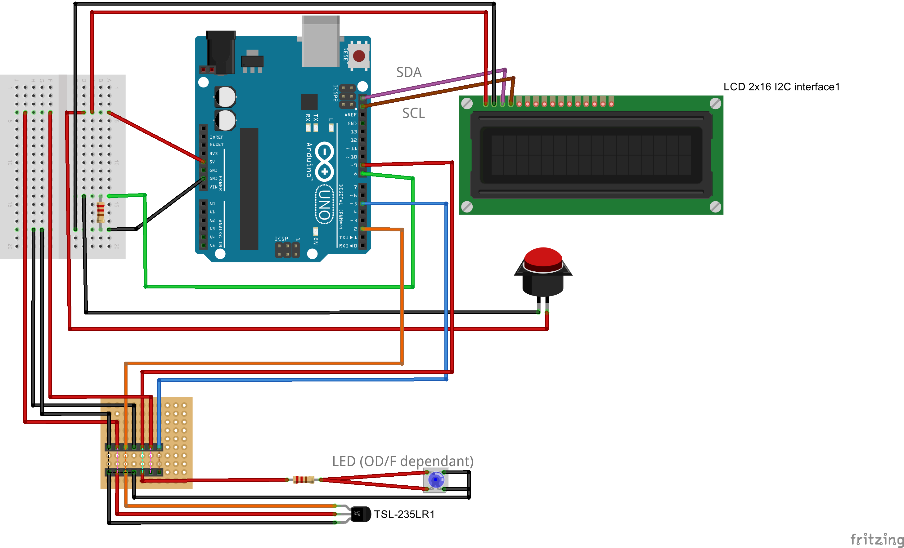
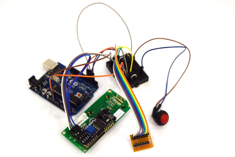
| + | | [[File:Aachen_ODF_2.JPG|300px]] || Then connect the button to 5V on the one side, and to GND via a resistor on the other side. Connect this side also to port __ on your Arduino. This will sense the blank. Next connect the display to the Arduino and our connector. See the Fritzing diagram at the bottom for a detailed information. | ||
| + | |- | ||
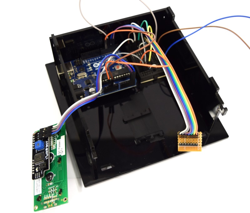
| + | | [[File:Aachen_ODF_13.JPG|300px]] || Now put everything into the case and ... | ||
| + | |- | ||
| + | | [[File:Aachen_ODF_6.JPG|300px]] || ... also place the cuvette holder into the device. Attach the display to the device lid and close the casing. | ||
| + | |- | ||
| + | | [[File:Aachen_ODF_7.JPG|300px]] || Congratulations! You have finished constructing your own OD/F device! | ||
| + | |} | ||
{{Team:Aachen/Footer}} | {{Team:Aachen/Footer}} | ||
Revision as of 13:11, 14 October 2014
|
|
|
 "
"
