Team:Aachen/Project/2D Biosensor
From 2014.igem.org
(→Medium) |
(→Development & Optimization) |
||
| Line 118: | Line 118: | ||
<span class="anchor" id="biosensordevelopment"></span> | <span class="anchor" id="biosensordevelopment"></span> | ||
| - | === | + | === Equipment and medium selection === |
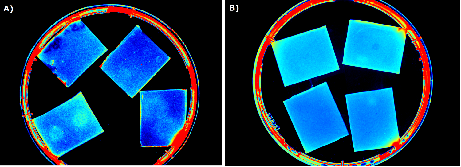
{{Team:Aachen/FigureFloat|Aachen_ILOV_GFP_HM_1,5h.png|title=iLOV and GFP in the Gel Doc<sup>TM</sup>|subtitle=Sensor cells producing iLOV (A) and GFP (B) 1.5 h after induction.|left|width=500px}} | {{Team:Aachen/FigureFloat|Aachen_ILOV_GFP_HM_1,5h.png|title=iLOV and GFP in the Gel Doc<sup>TM</sup>|subtitle=Sensor cells producing iLOV (A) and GFP (B) 1.5 h after induction.|left|width=500px}} | ||
| Line 146: | Line 146: | ||
glycerol. Storage at -20°C resulted in the loss of our sensor cells. Adding 5-10% (v/v) glycerol ensured survival of the sensor cells, but resulted in an expression stop of fluorescence proteins. Hence, we concluded that long time storage of the sensor chips is not possible under the tested conditions. However, it is possible to store 'ready-to-use' sensor chips for 2 days at 4°C when using LB medium and storage for 5 days was possible with chips made from TB medium. | glycerol. Storage at -20°C resulted in the loss of our sensor cells. Adding 5-10% (v/v) glycerol ensured survival of the sensor cells, but resulted in an expression stop of fluorescence proteins. Hence, we concluded that long time storage of the sensor chips is not possible under the tested conditions. However, it is possible to store 'ready-to-use' sensor chips for 2 days at 4°C when using LB medium and storage for 5 days was possible with chips made from TB medium. | ||
| - | === | + | === Optimal agarose concentration for the sensor chip === |
For the sensor chip manufacturing, a concentration of 1.5% agarose was found to be optimal. When agarose concentrations below 1.5% (w/v) were used the sensor chips were easily damaged and were not transportable. Agar concentrations over 1.5% (w/v) had to be avoided, because the agarose started to solidify before it could be poured into the chip casting mold. | For the sensor chip manufacturing, a concentration of 1.5% agarose was found to be optimal. When agarose concentrations below 1.5% (w/v) were used the sensor chips were easily damaged and were not transportable. Agar concentrations over 1.5% (w/v) had to be avoided, because the agarose started to solidify before it could be poured into the chip casting mold. | ||
Agarose was chosen over agar, because of a more even linkage between molecules resulting in a better chip homogenity. In addition, agarose reduced diffusion of inducer molecules through the chip. A reduction in diffusion was desired in order to achieve distinct fluorescent spots on the sensor chips. | Agarose was chosen over agar, because of a more even linkage between molecules resulting in a better chip homogenity. In addition, agarose reduced diffusion of inducer molecules through the chip. A reduction in diffusion was desired in order to achieve distinct fluorescent spots on the sensor chips. | ||
| - | === | + | === Optimal chip configuration === |
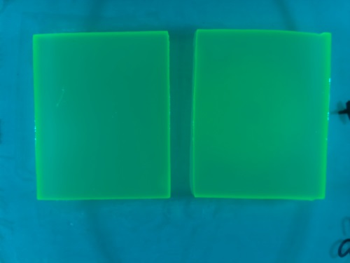
{{Team:Aachen/FigureFloat|Aachen_2_chipform.jpg|title=Chips made using the closed mold|subtitle=With this method we encounter problems due to frequent bubble formation.|left|width=500px}} | {{Team:Aachen/FigureFloat|Aachen_2_chipform.jpg|title=Chips made using the closed mold|subtitle=With this method we encounter problems due to frequent bubble formation.|left|width=500px}} | ||
Various approaches were tried for production of sensor chips with reproducable quality. The first approach was to cast every sensor chip individually. In order to achieve a plain chip surface, which was required for high quality images, we tried to cast the sensor chips between four microscope slides. This approach had to be rejected, because the agar was too liquid. In a second try, we produced a closed mold into which liquid agar was injected using a pipette, but we encountered a high number of bubbles in the chips when using this method. Bubbles in the sensor chips resulted in problems during fluorescence evalutaion. | Various approaches were tried for production of sensor chips with reproducable quality. The first approach was to cast every sensor chip individually. In order to achieve a plain chip surface, which was required for high quality images, we tried to cast the sensor chips between four microscope slides. This approach had to be rejected, because the agar was too liquid. In a second try, we produced a closed mold into which liquid agar was injected using a pipette, but we encountered a high number of bubbles in the chips when using this method. Bubbles in the sensor chips resulted in problems during fluorescence evalutaion. | ||
| Line 157: | Line 157: | ||
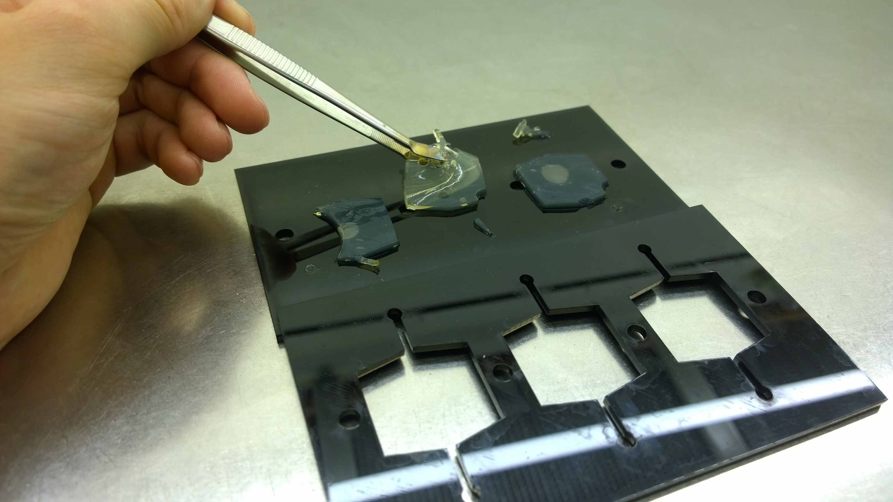
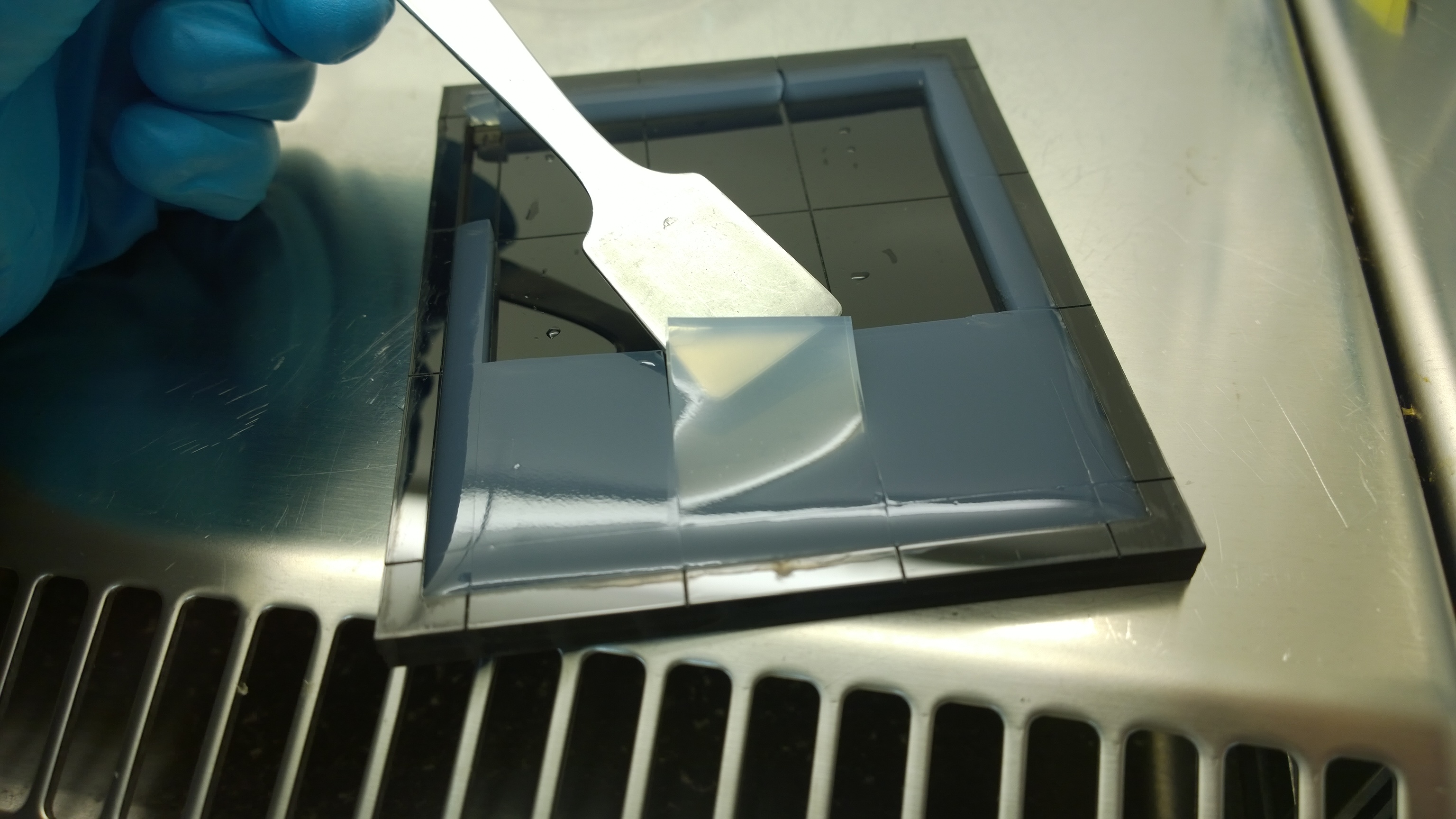
Finally, we used an open mold into which the agar was poured right after mixing with the sensor cells. When the agar had solidified the chips were cut out along precast indentations in the casting mold. An advantage of the open mold was the ability to simultaneously produce nine sensor chips while the surface tension of the liquid agar ensured a plane chip surface. | Finally, we used an open mold into which the agar was poured right after mixing with the sensor cells. When the agar had solidified the chips were cut out along precast indentations in the casting mold. An advantage of the open mold was the ability to simultaneously produce nine sensor chips while the surface tension of the liquid agar ensured a plane chip surface. | ||
| - | === Induction === | + | === Induction of sensor chip === |
For artificially induction of our molecular detection constructs we simluated the presence of ''P. aeruginosa'' by use of IPTG or 3-oxo-C12 HSL. | For artificially induction of our molecular detection constructs we simluated the presence of ''P. aeruginosa'' by use of IPTG or 3-oxo-C12 HSL. | ||
A minimal pipetting volume was desired for induction, because initial experiments showed that diffusion of the inducers through the chip hindered formation of distinct spots on the chips. Due to the pipetts available the lowest volume we could pipett was limitted to 0.2 µL . | A minimal pipetting volume was desired for induction, because initial experiments showed that diffusion of the inducers through the chip hindered formation of distinct spots on the chips. Due to the pipetts available the lowest volume we could pipett was limitted to 0.2 µL . | ||
Revision as of 17:51, 17 October 2014
|
|
|
|
|
|
 "
"
