Team:Aachen/Project/Model
From 2014.igem.org
(→Modeling) |
(→Modeling) |
||
| (3 intermediate revisions not shown) | |||
| Line 21: | Line 21: | ||
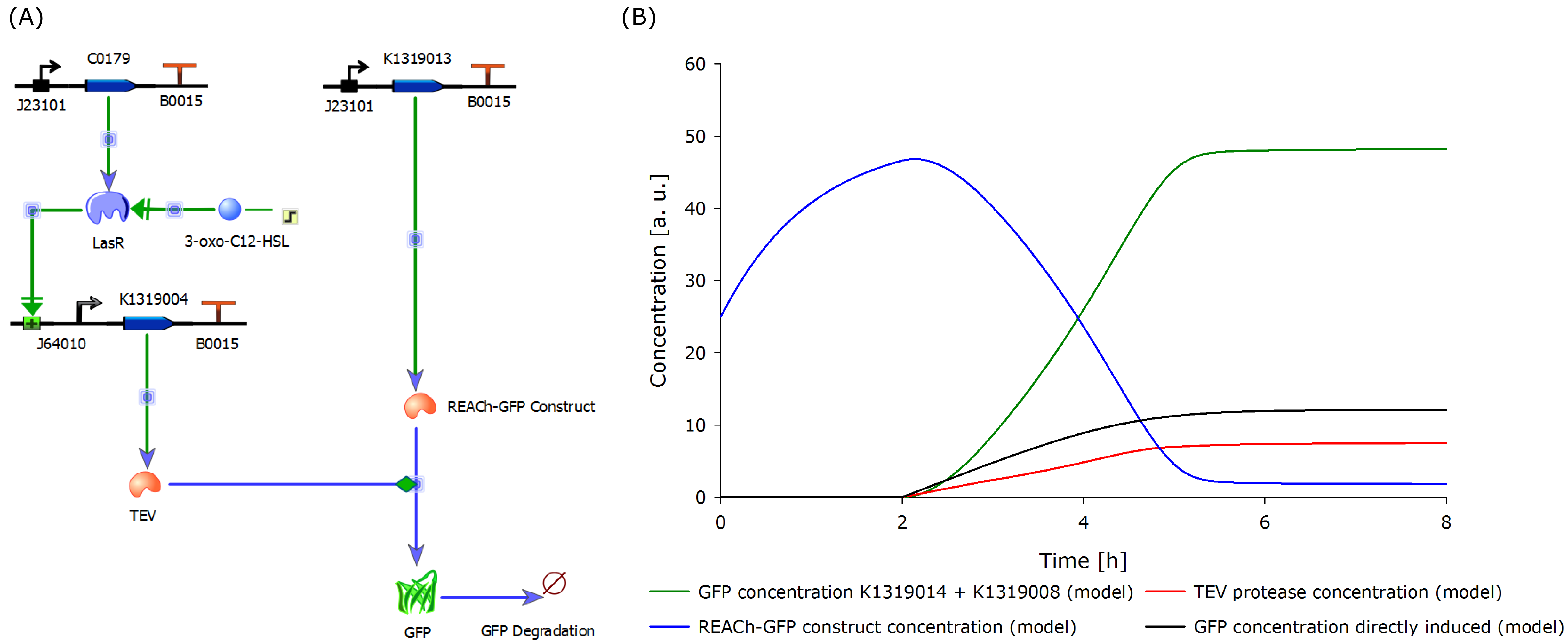
{{Team:Aachen/Figure|Aachen_Model_merged.png|align=center|title=Model of our molecular approach in TinkerCell (A) and the output over time (B)|subtitle=The molecular setup of the novel 3-oxo-C<sub>12</sub>-HSL inducible biosensor (A) yields results indicating a strong and fast fluorescence output after induction (B). A directly inducible system was modeled and added to the plot for comparison.|width=1000px}} | {{Team:Aachen/Figure|Aachen_Model_merged.png|align=center|title=Model of our molecular approach in TinkerCell (A) and the output over time (B)|subtitle=The molecular setup of the novel 3-oxo-C<sub>12</sub>-HSL inducible biosensor (A) yields results indicating a strong and fast fluorescence output after induction (B). A directly inducible system was modeled and added to the plot for comparison.|width=1000px}} | ||
</center> | </center> | ||
| - | |||
In the figure displayed above, we compare the response time of the fluorescence signal between our theoretical system and a traditional biosensor, we included a direct expression of GFP in the same plot. In the results shown above, the strength of the promoter used for the direct GFP expression (traditional approach) is twice as high as the strength of the promoter upstream of the TEV coding sequence in our new approach. Despite a weaker promoter, a '''higher GFP concentration is generated in the model of the novel biosensor''', predicting a quicker response time of our system. | In the figure displayed above, we compare the response time of the fluorescence signal between our theoretical system and a traditional biosensor, we included a direct expression of GFP in the same plot. In the results shown above, the strength of the promoter used for the direct GFP expression (traditional approach) is twice as high as the strength of the promoter upstream of the TEV coding sequence in our new approach. Despite a weaker promoter, a '''higher GFP concentration is generated in the model of the novel biosensor''', predicting a quicker response time of our system. | ||
| Line 33: | Line 32: | ||
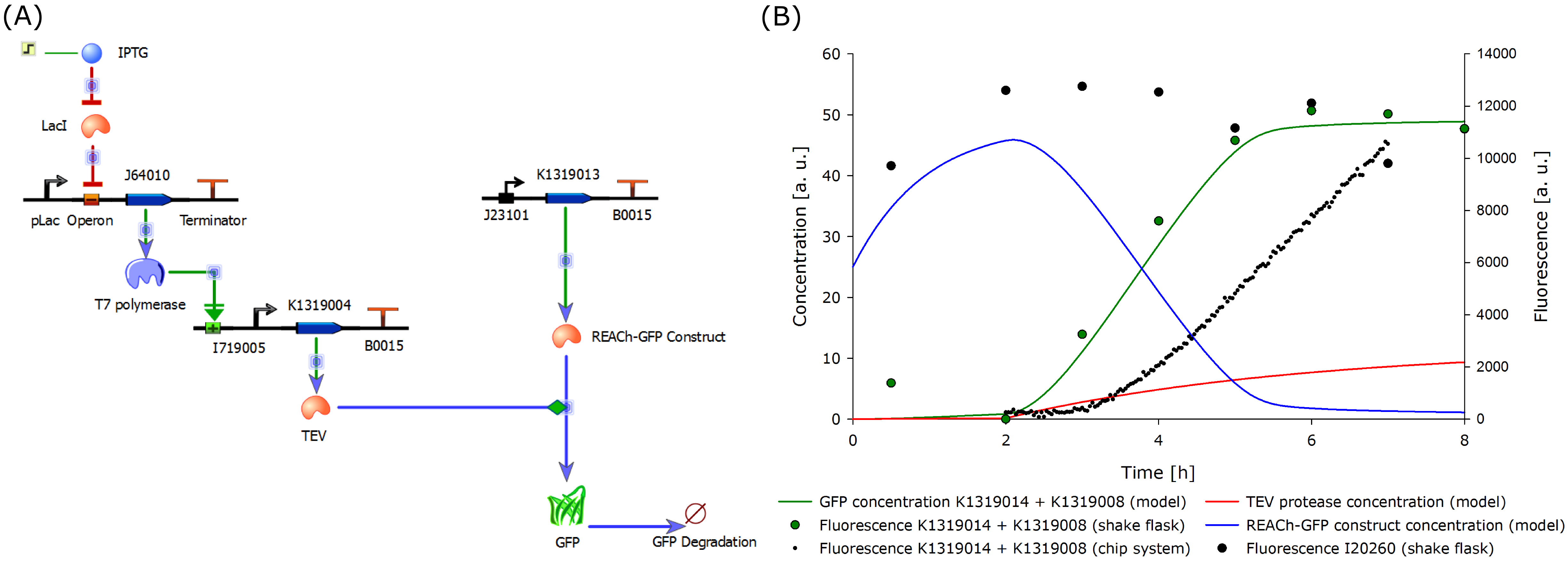
{{Team:Aachen/Figure|Aachen_Model_IPTG_merged.png|align=center|title=Revised model of the molecular approach (A) and output over time (B).|subtitle=This model is for the IPTG-inducible double plasmid system (A) and the calculated output (B). Experimental data was included in the plot for comparison and data validation.|width=1000px}} | {{Team:Aachen/Figure|Aachen_Model_IPTG_merged.png|align=center|title=Revised model of the molecular approach (A) and output over time (B).|subtitle=This model is for the IPTG-inducible double plasmid system (A) and the calculated output (B). Experimental data was included in the plot for comparison and data validation.|width=1000px}} | ||
</center> | </center> | ||
| - | |||
The model was optimized to fit the data generated from the characterization experiment conducted in shake flasks. Additionally, the data from the characterization experiment of the double plasmid construct (K1319014 + K1319008) in the chip system was included in the plot above. The data was derived from the plate reader output of the four central spots of the chip. The background from the non-induced chip was substracted from the fluorescence response to correct the data and avoid effects from cell growth leading to wrong signal strengths. The development of the fluorescence is presented [https://2014.igem.org/Team:Aachen/Project/FRET_Reporter#reachachievementschip here]. | The model was optimized to fit the data generated from the characterization experiment conducted in shake flasks. Additionally, the data from the characterization experiment of the double plasmid construct (K1319014 + K1319008) in the chip system was included in the plot above. The data was derived from the plate reader output of the four central spots of the chip. The background from the non-induced chip was substracted from the fluorescence response to correct the data and avoid effects from cell growth leading to wrong signal strengths. The development of the fluorescence is presented [https://2014.igem.org/Team:Aachen/Project/FRET_Reporter#reachachievementschip here]. | ||
| Line 45: | Line 43: | ||
==References== | ==References== | ||
* Chandran, D., Bergmann, F. T., & Sauro, H. M. (2009). TinkerCell: modular CAD tool for synthetic biology. Journal of biological engineering, 3(1), 19. doi: 10.1186/1754-1611-3-19 | * Chandran, D., Bergmann, F. T., & Sauro, H. M. (2009). TinkerCell: modular CAD tool for synthetic biology. Journal of biological engineering, 3(1), 19. doi: 10.1186/1754-1611-3-19 | ||
| - | |||
{{Team:Aachen/Footer}} | {{Team:Aachen/Footer}} | ||
Latest revision as of 03:26, 18 October 2014
|
|
 "
"


