Team:Aachen/Project/2D Biosensor
From 2014.igem.org
(→Achievements) |
(→Achievements) |
||
| (34 intermediate revisions not shown) | |||
| Line 116: | Line 116: | ||
<span class="anchor" id="biosensordevelopment"></span> | <span class="anchor" id="biosensordevelopment"></span> | ||
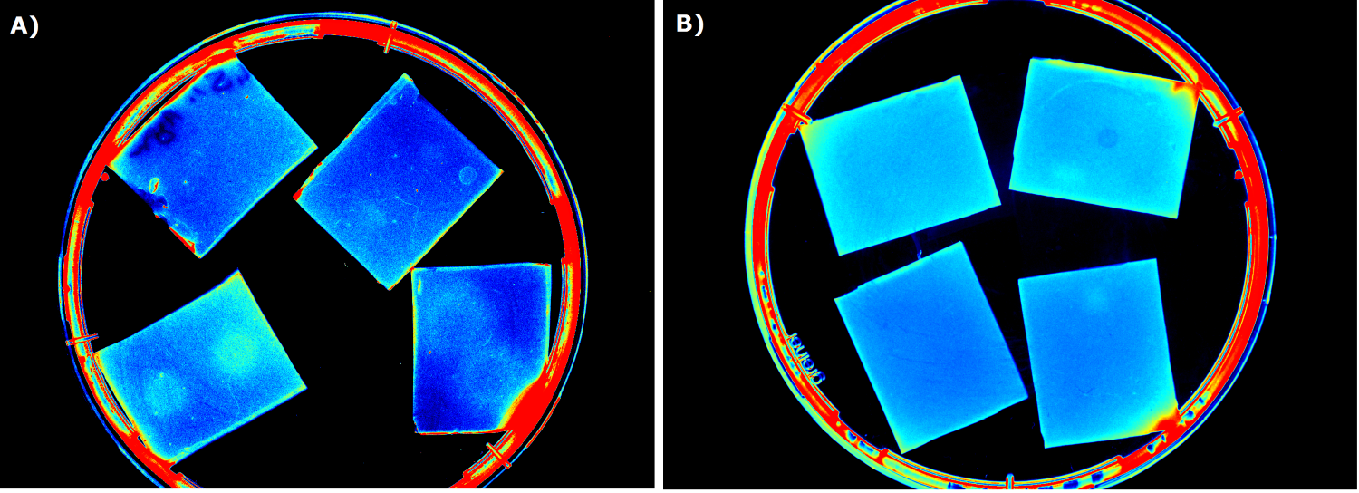
| - | {{Team:Aachen/FigureFloat|Aachen_ILOV_GFP_HM_1,5h.png|title=iLOV and GFP in the Gel Doc<sup>TM</sup>|subtitle=Sensor cells producing iLOV (A) and GFP (B) 1.5 h after induction.|left|width=500px}} | + | {{Team:Aachen/FigureFloat|Aachen_ILOV_GFP_HM_1,5h.png|title=iLOV and GFP in the Gel Doc<sup>TM</sup>|subtitle=Sensor cells producing iLOV (K1319042, A) and GFP (B) 1.5 h after induction.|left|width=500px}} |
=== Equipment and medium selection === | === Equipment and medium selection === | ||
| - | Our first approach (before developing our own device) was to use the Molecular Imager® Gel Doc™ XR+ from BIO-RAD in our lab to detect fluorescence. This device uses UV and white light illuminators. However, only two different filters were available for the excitation light wavelength, which resulted in very limited possibilities for the excitation of fluorescent molecules. For example, it was possible to detect the expression of iLOV in our sensor chips, but not the expression of GFP. Hence, the '''Gel Doc™ was not suitable for our project'''. | + | Our first approach (before developing our own device) was to use the Molecular Imager® Gel Doc™ XR+ from BIO-RAD in our lab to detect fluorescence. This device uses UV and white light illuminators. However, only two different filters were available for the excitation light wavelength, which resulted in very limited possibilities for the excitation of fluorescent molecules. For example, it was possible to detect the expression of iLOV (K1319042) in our sensor chips, but not the expression of GFP. Hence, the '''Gel Doc™ was not suitable for our project'''. |
{{Team:Aachen/FigureFloat|Aachen_Chip_medium_geldoc.png|title=Differend medium in the Gel Doc™|subtitle=complex media exhibited high background fluorescence while less back- ground fluorescence was observed with the minimal media (HM, M9, NA).|right|width=500px}} | {{Team:Aachen/FigureFloat|Aachen_Chip_medium_geldoc.png|title=Differend medium in the Gel Doc™|subtitle=complex media exhibited high background fluorescence while less back- ground fluorescence was observed with the minimal media (HM, M9, NA).|right|width=500px}} | ||
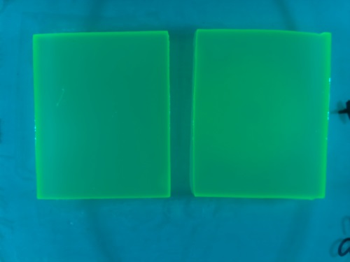
{{Team:Aachen/FigureFloat|Aachen_5days_K131026_neb_tb_1,5h.jpg |title=Testing our chips' shelf-life|subtitle= Chips of [http://parts.igem.org/Part:BBa_K131026 K131026] in NEB were stored five days at 4°C. The right chip was induced with 0.2 µL of 500 µg/mL HSL and an image was taken after 1.5 h.|left|width=500px}} | {{Team:Aachen/FigureFloat|Aachen_5days_K131026_neb_tb_1,5h.jpg |title=Testing our chips' shelf-life|subtitle= Chips of [http://parts.igem.org/Part:BBa_K131026 K131026] in NEB were stored five days at 4°C. The right chip was induced with 0.2 µL of 500 µg/mL HSL and an image was taken after 1.5 h.|left|width=500px}} | ||
| Line 164: | Line 164: | ||
{{Team:Aachen/FigureFloat|Aachen_K1319042_Platereader.gif|title=Testing K1319042 in our sensor chips|subtitle=Sensor chips based on [http://parts.igem.org/Part:BBa_K1319042 K1319042] were investigated for fluorescence using a plate reader. Blue color indicates the absence of fluorescence, while red color indicates fluorescence. The upper chip was not induced, while the lower chip was induced with IPTG (2.0 µL, 100mM).|width=260px}} | {{Team:Aachen/FigureFloat|Aachen_K1319042_Platereader.gif|title=Testing K1319042 in our sensor chips|subtitle=Sensor chips based on [http://parts.igem.org/Part:BBa_K1319042 K1319042] were investigated for fluorescence using a plate reader. Blue color indicates the absence of fluorescence, while red color indicates fluorescence. The upper chip was not induced, while the lower chip was induced with IPTG (2.0 µL, 100mM).|width=260px}} | ||
| - | |||
=== Testing our Sensor Chips in a Plate Reader === | === Testing our Sensor Chips in a Plate Reader === | ||
To establish a prove-of-principle for our sensor chip design, we used our construct [http://parts.igem.org/Part:BBa_K1319042 K1319042], an IPTG inducible iLOV. ''E. coli'' cells carrying the this construct were introduced into sensor chips and fluorescence was measured every 15 minutes after induction with 2 µL of 100 mM IPTG. The results are displayed on the left. | To establish a prove-of-principle for our sensor chip design, we used our construct [http://parts.igem.org/Part:BBa_K1319042 K1319042], an IPTG inducible iLOV. ''E. coli'' cells carrying the this construct were introduced into sensor chips and fluorescence was measured every 15 minutes after induction with 2 µL of 100 mM IPTG. The results are displayed on the left. | ||
We observed a distinct difference in fluorescence between the non-induced chip (top) and the induced chip (bottom). The middle of the bottom chip started to exhibit a clear and visible fluorescence that increased over time and spread outwards. The top chip, however, also showed an increase in the measured fluorescence over time which was primarily due to the leaky promoter and background fluorescence. | We observed a distinct difference in fluorescence between the non-induced chip (top) and the induced chip (bottom). The middle of the bottom chip started to exhibit a clear and visible fluorescence that increased over time and spread outwards. The top chip, however, also showed an increase in the measured fluorescence over time which was primarily due to the leaky promoter and background fluorescence. | ||
| + | |||
| + | {{Team:Aachen/FigureFloatRight|Aachen_K131026_Platereader.gif|title=Testing K131026 in our sensor chips|subtitle=Sensor chips based on [http://parts.igem.org/Part:BBa_K131026 K131026] were investigated for fluorescence using a plate reader. Blue color indicates the absence of fluorescence, while red color indicates fluorescence. The lower chip was induced with with 3-oxo-C{{sub|12}}-HSL (0.2 µL, 500 µg/mL).|width=360px}} | ||
=== Detecting 3-oxo-C{{sub|12}}-HSL with Sensor Chips === | === Detecting 3-oxo-C{{sub|12}}-HSL with Sensor Chips === | ||
| - | |||
| - | |||
In an initial attempt to detect 3-oxo-C{{sub|12}}-HSL, we incorporated the [http://parts.igem.org/Part:BBa_K131026 K131026] construct generated by the 2008 iGEM Team Calgary in our sensor chips. This construct generates a fluorescent signal based on GFP in presence of 3-oxo-C{{sub|12}}-HSL molecules produced by ''P. aeruginosa'' during quorum sensing (Jimenez, Koch, Thompson et al., 2012). First, we tested the construct by direct induction with 3-oxo-C{{sub|12}}-HSL (0.2 µL, 500 µg/mL). The fluorescence measurement was taken every 15 minutes with an excitation wavelength of 496 nm and an emission wavelength of 516 nm. The results of this test are shown on the right. | In an initial attempt to detect 3-oxo-C{{sub|12}}-HSL, we incorporated the [http://parts.igem.org/Part:BBa_K131026 K131026] construct generated by the 2008 iGEM Team Calgary in our sensor chips. This construct generates a fluorescent signal based on GFP in presence of 3-oxo-C{{sub|12}}-HSL molecules produced by ''P. aeruginosa'' during quorum sensing (Jimenez, Koch, Thompson et al., 2012). First, we tested the construct by direct induction with 3-oxo-C{{sub|12}}-HSL (0.2 µL, 500 µg/mL). The fluorescence measurement was taken every 15 minutes with an excitation wavelength of 496 nm and an emission wavelength of 516 nm. The results of this test are shown on the right. | ||
| Line 178: | Line 177: | ||
A distinct fluorescence signal was observed on the induced chip (bottom) compared to the non-induced chip (top). | A distinct fluorescence signal was observed on the induced chip (bottom) compared to the non-induced chip (top). | ||
Fluorescence started in the middle of the chip, the point of induction, and then extended outwards while growing in intesnity. The basal level of fluorescence was attributed to leakiness of the promoter and general background fluorescence of growing ''E. coli'' cells. In the induced chip (bottom), the background fluorescence was lower than in the non-induced chip (top) because the signal masked the noise. The difference between the induced and non-induced chips indicates a clear response to the HSL and proofed the ability of our 2D sensor chip design to detect HSLs produced by ''Pseudomonas aeruginosa''. | Fluorescence started in the middle of the chip, the point of induction, and then extended outwards while growing in intesnity. The basal level of fluorescence was attributed to leakiness of the promoter and general background fluorescence of growing ''E. coli'' cells. In the induced chip (bottom), the background fluorescence was lower than in the non-induced chip (top) because the signal masked the noise. The difference between the induced and non-induced chips indicates a clear response to the HSL and proofed the ability of our 2D sensor chip design to detect HSLs produced by ''Pseudomonas aeruginosa''. | ||
| - | |||
{{Team:Aachen/FigureFloat|Aachen_I746909_slower_reduced.gif|title=IPTG-inducible superfolder GFP (I746909) in sensor chips|subtitle=Expression of superfolder GFP ([http://parts.igem.org/Part:BBa_I746909 I746909]) was induced by the addition of IPTG (2 µL, 100mM) on the right chip. The left chip was not induced.|width=480px}} | {{Team:Aachen/FigureFloat|Aachen_I746909_slower_reduced.gif|title=IPTG-inducible superfolder GFP (I746909) in sensor chips|subtitle=Expression of superfolder GFP ([http://parts.igem.org/Part:BBa_I746909 I746909]) was induced by the addition of IPTG (2 µL, 100mM) on the right chip. The left chip was not induced.|width=480px}} | ||
| - | |||
=== Detecting IPTG with Sensor Chips === | === Detecting IPTG with Sensor Chips === | ||
| Line 194: | Line 191: | ||
| - | {{Team:Aachen/FigureFloatRight|Aachen_K131026_HSLdetection_slow.gif|title=Detection of 3-oxo-C{{sub|12}}-HSL with K131026|subtitle=0.2 µL of 3-oxo-C{{sub|12}}-HSL was placed in the middle of | + | |
| + | {{Team:Aachen/FigureFloatRight|Aachen_K131026_HSLdetection_slow.gif|title=Detection of 3-oxo-C{{sub|12}}-HSL with K131026|subtitle=0.2 µL of 3-oxo-C{{sub|12}}-HSL was placed in the middle of a sensor chip based on [http://parts.igem.org/Part:BBa_K131026 K131026] followed by incubation at 37°C in ''WatsOn''.|width=480px}} | ||
===Detecting the 3-oxo-C{{sub|12}}-HSL with K131026 in our Sensor Chips using ''WatsOn''=== | ===Detecting the 3-oxo-C{{sub|12}}-HSL with K131026 in our Sensor Chips using ''WatsOn''=== | ||
| + | |||
The next step towards the final goal of detecting living cells of ''Pseudomonas aeruginosa'' was to reproduce the detection of 3-oxo-C{{sub|12}}-HSL, already established in the plate reader, in our own [https://2014.igem.org/Team:Aachen/Project/Measurement_Device ''WatsOn''] device. Therefore, we again used ''E. coli'' BL21(DE3) cells carrying [http://parts.igem.org/Part:BBa_K131026 K131026] and induced with 0.2 µL 3-oxo-C{{sub|12}}-HSL of a concentration of 500 µg/mL. In the clip displayed on the left, the right chip was induced and - as a negative control - the left chip was not induced. Pictures were taken every four minutes. | The next step towards the final goal of detecting living cells of ''Pseudomonas aeruginosa'' was to reproduce the detection of 3-oxo-C{{sub|12}}-HSL, already established in the plate reader, in our own [https://2014.igem.org/Team:Aachen/Project/Measurement_Device ''WatsOn''] device. Therefore, we again used ''E. coli'' BL21(DE3) cells carrying [http://parts.igem.org/Part:BBa_K131026 K131026] and induced with 0.2 µL 3-oxo-C{{sub|12}}-HSL of a concentration of 500 µg/mL. In the clip displayed on the left, the right chip was induced and - as a negative control - the left chip was not induced. Pictures were taken every four minutes. | ||
| - | |||
The result was a clear replication of the success of the plate reader experiment. The induced chip showed a clear fluorescence response eminating from the center, where the induction with HSL took place. This demonstrated the ability of not only our sensor chip technology but also our measurement device ''WatsOn to successfully'' detect 3-oxo-C{{sub|12}}-HSL. | The result was a clear replication of the success of the plate reader experiment. The induced chip showed a clear fluorescence response eminating from the center, where the induction with HSL took place. This demonstrated the ability of not only our sensor chip technology but also our measurement device ''WatsOn to successfully'' detect 3-oxo-C{{sub|12}}-HSL. | ||
| - | |||
| + | |||
| + | |||
| + | {{Team:Aachen/FigureFloat|Aachen_K131026_Pseudomonas_aeruginosa_detection.gif|title=Detection of ''Pseudomonas aeruginosa'' with K131026|subtitle=Direct detection of ''Pseudomonas aeruginosa'' on sensor chips based on [http://parts.igem.org/Part:BBa_K131026 K131026].|width=480px}} | ||
===Detecting ''Pseudomonas aeruginosa'' with K131026 in our Sensor Chip with ''WatsOn''=== | ===Detecting ''Pseudomonas aeruginosa'' with K131026 in our Sensor Chip with ''WatsOn''=== | ||
| - | |||
| + | After establishing the successful detection of 3-oxo-C{{sub|12}}-HSLs with our sensor chips the next step was to detect living cells of ''Pseudomonas aeruginosa'' with our measurement device ''WatsOn''. Therefore sensor chips based on [http://parts.igem.org/Part:BBa_K131026 K131026] were prepared and the right chip was induced with 0.2 µL of a ''Pseudomonas aeruginosa'' culture while the left chip was not induced (Detection of 3-oxo-C12 HSL with K131026, displayed below). On the induced chip, a clear fluorescence signal was visible in response to ''P. aeruginosa''. The fluorescence signal emerged outward from the induction point and showed a significant difference to the non-induced chip. The results clearly demonstrate the ability of our sensor chip technology and our measurement device ''WatsOn'' to detect ''P. aeruginosa''! | ||
{{Team:Aachen/BlockSeparator}} | {{Team:Aachen/BlockSeparator}} | ||
| Line 232: | Line 232: | ||
* Jimenez, P. N., Koch, G., Thompson, J. A., Xavier, K. B., Cool, R. H., & Quax, W. J. (2012). The Multiple Signaling Systems Regulating Virulence in ''Pseudomonas aeruginosa''. Microbiology and Molecular Biology Reviews, 76(1), 46-65. Available online at http://www.ncbi.nlm.nih.gov/pmc/articles/PMC3294424/#B63. | * Jimenez, P. N., Koch, G., Thompson, J. A., Xavier, K. B., Cool, R. H., & Quax, W. J. (2012). The Multiple Signaling Systems Regulating Virulence in ''Pseudomonas aeruginosa''. Microbiology and Molecular Biology Reviews, 76(1), 46-65. Available online at http://www.ncbi.nlm.nih.gov/pmc/articles/PMC3294424/#B63. | ||
| + | |||
{{Team:Aachen/Footer}} | {{Team:Aachen/Footer}} | ||
Latest revision as of 03:43, 18 October 2014
|
|
|
|
|
|
 "
"
