Team:Aachen/Project/Measurement Device
From 2014.igem.org
(→WatsOn) |
(→Achievements) |
||
| (51 intermediate revisions not shown) | |||
| Line 5: | Line 5: | ||
= ''WatsOn'' = | = ''WatsOn'' = | ||
| - | |||
| - | |||
| - | + | <html><br></html> | |
| + | {{Team:Aachen/FigureFloatRight|Aachen_Device_11.jpg|title=''WatsOn''|subtitle= |width=360px}} | ||
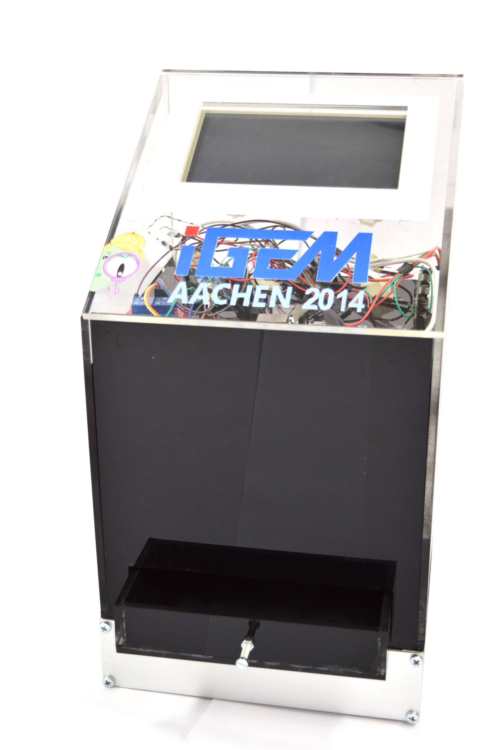
| + | The ''WatsOn'' device aims to answer the central question "What's on the chip?". The device is designed to incubate the sensing cells and capture images. <html><br></html>The interactive ''WatsOn'' software enables the end user not only to take images and time lapse shootings, but also analyzes the images and visualizes the presence/absence of a pathogen. | ||
| - | The | + | The construction manual and the technical details are published on the [https://2014.igem.org/Team:Aachen/Notebook/Engineering/WatsOn#watsondiy engineering page]. |
| - | + | ||
| - | + | ||
<html> | <html> | ||
<center> | <center> | ||
<ul class="menusmall-grid"> | <ul class="menusmall-grid"> | ||
| - | |||
| - | <li> | + | <li style="margin-bottom:5px;margin-top:5px;"> |
<a class="menulink" href="https://2014.igem.org/Team:Aachen/Project/Measurement_Device#watsonapplication" style="color:black"> | <a class="menulink" href="https://2014.igem.org/Team:Aachen/Project/Measurement_Device#watsonapplication" style="color:black"> | ||
| - | <div class="menusmall-item menusmall-info" ><div class="menukachel"> | + | <div class="menusmall-item menusmall-info" ><div class="menukachel" style="top:25%; line-height:1.5em;">Modus Operandi</div></div> |
| - | <div class="menusmall-item menusmall-img" style="background: url(https://static.igem.org/mediawiki/2014 | + | <div class="menusmall-item menusmall-img" style="background: url(https://static.igem.org/mediawiki/2014/c/c7/Aachen_WatsOn_easy.png); norepeat scroll 0% 0% transparent; background-size:100%"> |
</div> | </div> | ||
</a> | </a> | ||
</li> | </li> | ||
| - | <li> | + | <li style="margin-bottom:5px;margin-top:5px;"> |
<a class="menulink" href="https://2014.igem.org/Team:Aachen/Project/Measurement_Device#watsonhardware" style="color:black"> | <a class="menulink" href="https://2014.igem.org/Team:Aachen/Project/Measurement_Device#watsonhardware" style="color:black"> | ||
| - | <div class="menusmall-item menusmall-info" ><div class="menukachel">Hardware</div></div> | + | <div class="menusmall-item menusmall-info" ><div class="menukachel" style="top:35%; line-height:1.5em;">Hardware</div></div> |
<div class="menusmall-item menusmall-img" style="background: url(https://static.igem.org/mediawiki/2014/5/59/Aachen_14-10-16_Hardware_button_iNB.png); norepeat scroll 0% 0% transparent; background-size:100%"> | <div class="menusmall-item menusmall-img" style="background: url(https://static.igem.org/mediawiki/2014/5/59/Aachen_14-10-16_Hardware_button_iNB.png); norepeat scroll 0% 0% transparent; background-size:100%"> | ||
</div> | </div> | ||
</a> | </a> | ||
</li> | </li> | ||
| + | </ul> | ||
| + | <ul class="menusmall-grid"> | ||
<li> | <li> | ||
<a class="menulink" href="https://2014.igem.org/Team:Aachen/Project/Measurement_Device#watsonsoftware" style="color:black"> | <a class="menulink" href="https://2014.igem.org/Team:Aachen/Project/Measurement_Device#watsonsoftware" style="color:black"> | ||
| - | <div class="menusmall-item menusmall-info" ><div class="menukachel">Software</div></div> | + | <div class="menusmall-item menusmall-info" ><div class="menukachel" style="top:35%; line-height:1.5em;">Software</div></div> |
<div class="menusmall-item menusmall-img" style="background: url(https://static.igem.org/mediawiki/2014/1/13/Aachen_14-10-16_Software_button_iNB.png); norepeat scroll 0% 0% transparent; background-size:100%"> | <div class="menusmall-item menusmall-img" style="background: url(https://static.igem.org/mediawiki/2014/1/13/Aachen_14-10-16_Software_button_iNB.png); norepeat scroll 0% 0% transparent; background-size:100%"> | ||
</div> | </div> | ||
| Line 45: | Line 44: | ||
<li> | <li> | ||
<a class="menulink" href="https://2014.igem.org/Team:Aachen/Project/Measurement_Device#watsonmeasurarty" style="color:black"> | <a class="menulink" href="https://2014.igem.org/Team:Aachen/Project/Measurement_Device#watsonmeasurarty" style="color:black"> | ||
| - | <div class="menusmall-item menusmall-info" ><div class="menukachel">Measurarty</div></div> | + | <div class="menusmall-item menusmall-info" ><div class="menukachel" style="top:35%; line-height:1.5em;">Measurarty</div></div> |
<div class="menusmall-item menusmall-img" style="background: url(https://static.igem.org/mediawiki/2014/2/21/Aachen_14-10-16_Measurarty_button_iNB.png); norepeat scroll 0% 0% transparent; background-size:100%"> | <div class="menusmall-item menusmall-img" style="background: url(https://static.igem.org/mediawiki/2014/2/21/Aachen_14-10-16_Measurarty_button_iNB.png); norepeat scroll 0% 0% transparent; background-size:100%"> | ||
</div> | </div> | ||
| Line 53: | Line 52: | ||
<li> | <li> | ||
<a class="menulink" href="https://2014.igem.org/Team:Aachen/Project/Measurement_Device#watsonachievements" style="color:black"> | <a class="menulink" href="https://2014.igem.org/Team:Aachen/Project/Measurement_Device#watsonachievements" style="color:black"> | ||
| - | <div class="menusmall-item menusmall-info" ><div class="menukachel">Achieve-<br/>ments</div></div> | + | <div class="menusmall-item menusmall-info" ><div class="menukachel" style="top:25%; line-height:1.5em;">Achieve-<br/>ments</div></div> |
<div class="menusmall-item menusmall-img" style="background: url(https://static.igem.org/mediawiki/2014/e/ef/Aachen_14-10-15_Medal_Cellocks_iNB.png); norepeat scroll 0% 0% transparent; background-size:100%"> | <div class="menusmall-item menusmall-img" style="background: url(https://static.igem.org/mediawiki/2014/e/ef/Aachen_14-10-15_Medal_Cellocks_iNB.png); norepeat scroll 0% 0% transparent; background-size:100%"> | ||
</div> | </div> | ||
</a> | </a> | ||
</li> | </li> | ||
| - | |||
</ul> | </ul> | ||
| Line 66: | Line 64: | ||
{{Team:Aachen/BlockSeparator}} | {{Team:Aachen/BlockSeparator}} | ||
| - | == | + | == Modus Operandi == |
<span class="anchor" id="watsonapplication"></span> | <span class="anchor" id="watsonapplication"></span> | ||
| - | {{Team:Aachen/Figure|How_two_use_watsOn_flowsheet_V7_ipo.png|title=How to use WatsOn|subtitle=This scheme illustrates handling WatsOn when testing the 2D biosensor chip for a fluorescent signal.|width=1000px}} | + | {{Team:Aachen/Figure|How_two_use_watsOn_flowsheet_V7_ipo.png|title=How to use ''WatsOn''|subtitle=This scheme illustrates handling ''WatsOn'' when testing the 2D biosensor chip for a fluorescent signal.|width=1000px}} |
| + | |||
{{Team:Aachen/BlockSeparator}} | {{Team:Aachen/BlockSeparator}} | ||
| Line 84: | Line 83: | ||
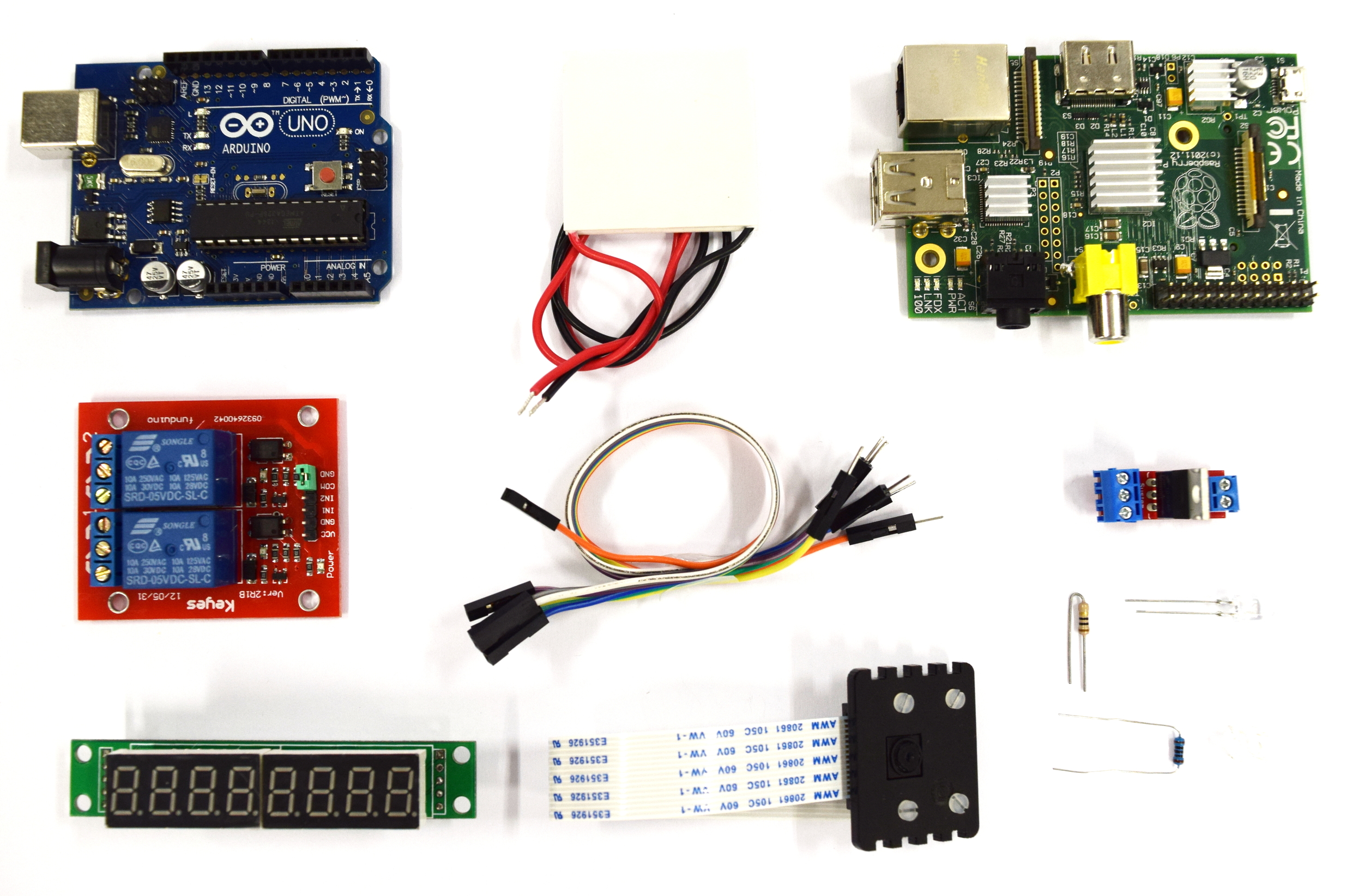
The electronic circuit is a combination of the components displayed in the image above. We combined the Raspberry Pi - a small single-board computer running a Linux operating system - and an Arduino board which is a programmable microcontroller. The Arduino operates the excitation LEDs and a Peltier heater for incubation. For taking images of the sensor chips we used the Raspberry Pi camera module which is directly connected to the board. | The electronic circuit is a combination of the components displayed in the image above. We combined the Raspberry Pi - a small single-board computer running a Linux operating system - and an Arduino board which is a programmable microcontroller. The Arduino operates the excitation LEDs and a Peltier heater for incubation. For taking images of the sensor chips we used the Raspberry Pi camera module which is directly connected to the board. | ||
| - | + | ''WatsOn'' is designed such that it can be easily copied. Our work heavily emphasizes the Open Source concept. Therefore a detailed description of all components and the wiring can be found in the [https://2014.igem.org/Team:Aachen/Notebook/Engineering/WatsOn#watsonhardware Engineering section of our Notebook]. | |
| + | |||
{{Team:Aachen/BlockSeparator}} | {{Team:Aachen/BlockSeparator}} | ||
| - | [[File:Aachen_14-10-16_Software_button_iNB.png|right|150px]] | + | <!-- [[File:Aachen_14-10-16_Software_button_iNB.png|right|150px]] --> |
== Software == | == Software == | ||
<span class="anchor" id="watsonsoftware"></span> | <span class="anchor" id="watsonsoftware"></span> | ||
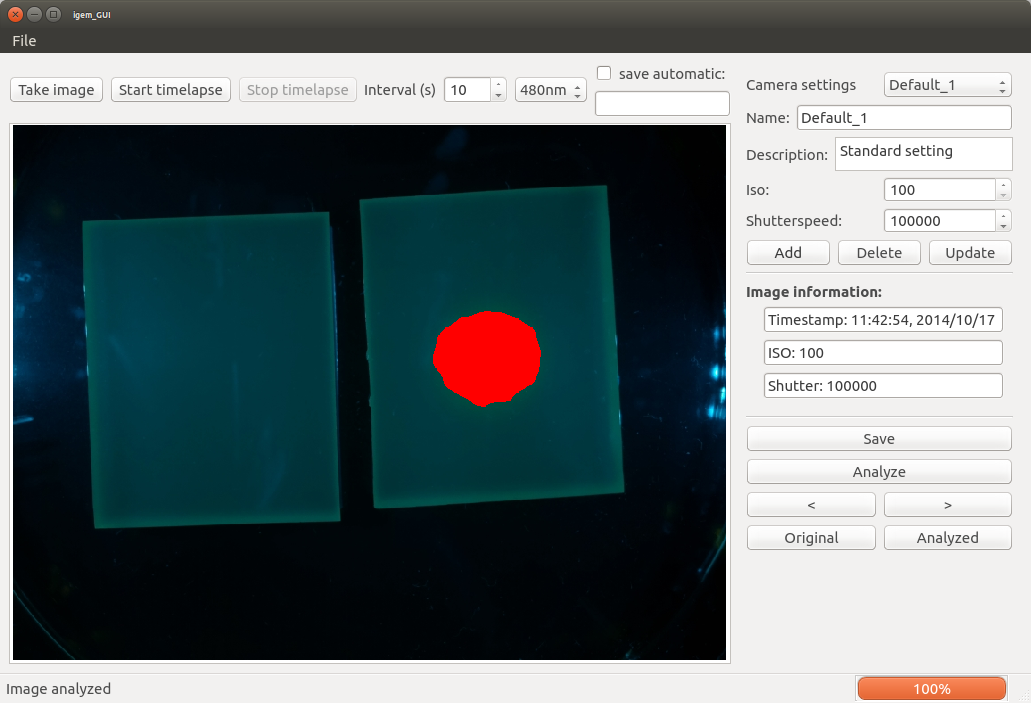
| - | + | {{Team:Aachen/FigureDual|Aachen_WatsOn_igem_GUI_originalImage.png|Aachen_WatsOn_igem_GUI_analyzedImage.png|title1=image taken with the camera |title2=analyzed image |subtitle1= |subtitle2= |width=500px}} | |
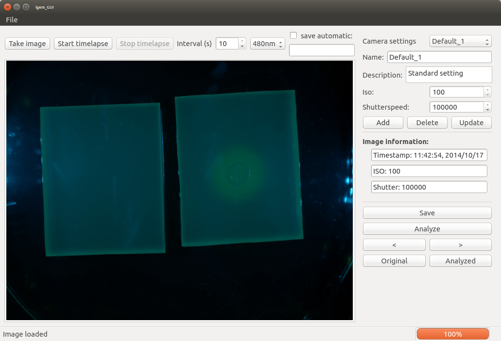
| - | The software is responsible for presenting a user interface on the display of the device and to take images with the LED wavelength selected by the user. Therefore it is separated into three single components: the graphical user interface (GUI) with a backend script running on the Raspberry Pi and the code on the Arduino board.<html><br/></html> | + | The ''WatsOn'' software is responsible for presenting a user interface on the display of the device and to take images with the LED wavelength selected by the user. Therefore, it is separated into three single components: the graphical user interface (GUI) with a backend script running on the Raspberry Pi and the code on the Arduino board.<html><br/></html> |
| - | The GUI(left image) provides the user with the option to take a single image or a time lapse shooting and specify parameters for the camera and the wavelength of the LEDs. The wavelength used in our device are 480nm for GFP and 450nm for iLOV. Furthermore the images are analysed for the presence or absence of P. aeruginosa by | + | The GUI (left image) provides the user with the option to take a single image or a time lapse shooting and specify parameters for the camera and the wavelength of the LEDs. The wavelength used in our device are 480nm for GFP and 450nm for iLOV. Furthermore, the images are analysed for the presence or absence of P. aeruginosa by processing the image with [https://2014.igem.org/Team:Aachen/Project/Measurement_Device#watsonmeasurarty Measurarty] and providing the user with a visual feedback (right image). All taken images can be saved to disk manually for single images and automatically for time lapse shootings.<html><br/></html> |
Further details on the software including the backend which gives the possibility of using the GUI remotely on a different device (e.g. notebook) in the same local network can be found here [https://2014.igem.org/Team:Aachen/Notebook/Engineering/WatsOn#watsonsoftware]. | Further details on the software including the backend which gives the possibility of using the GUI remotely on a different device (e.g. notebook) in the same local network can be found here [https://2014.igem.org/Team:Aachen/Notebook/Engineering/WatsOn#watsonsoftware]. | ||
| + | |||
{{Team:Aachen/BlockSeparator}} | {{Team:Aachen/BlockSeparator}} | ||
| Line 103: | Line 104: | ||
[[File:Aachen_14-10-16_Measurarty_button_iNB.png|right|150px]] | [[File:Aachen_14-10-16_Measurarty_button_iNB.png|right|150px]] | ||
| - | == Measurarty == | + | == ''Measurarty'' == |
<span class="anchor" id="watsonmeasurarty"></span> | <span class="anchor" id="watsonmeasurarty"></span> | ||
<center> | <center> | ||
| Line 109: | Line 110: | ||
</center> | </center> | ||
| - | Measurarty is the '''image analysis software''' of our device and is designed to allow an automatic segmentation and classification of our '''agar chip pictures'''. | + | ''Measurarty'' is the '''image analysis software''' of our device and is designed to allow an automatic segmentation and classification of our '''agar chip pictures'''. |
| - | Therefore, it | + | Therefore, it accepts an image from ''WatsOn'' as an input and produces an output image with pathogenic regions marked in red. |
This component mainly focuses on recognizing pathogens early, such that pure thresholding is not necessary. | This component mainly focuses on recognizing pathogens early, such that pure thresholding is not necessary. | ||
We therefore designed a pipeline and established a smoothness index to make statements about the pathogenity of a chip as early as possible, but also with as much certainty as possible. | We therefore designed a pipeline and established a smoothness index to make statements about the pathogenity of a chip as early as possible, but also with as much certainty as possible. | ||
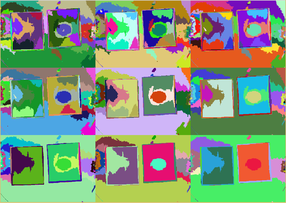
| - | A sample output of the segmentation is presented below, showing that the pipeline works as intended. | + | A sample output of the segmentation is presented below, showing that the pipeline works as intended.<html><br/></html> |
| + | The left half shows the original images from the device and the right half shows the same pictures with the detected pathogenic region analyzed by ''Measurarty''. | ||
| + | <center> | ||
| + | <div class="figure" style="float:{{{align|center}}}; margin: 0px 10px 10px 0px; border:{{{border|0px solid #aaa}}};width:{{{width|960px}}};padding:10px 10px 0px 0px;"> | ||
| + | {| | ||
| + | |<html> <img src="https://static.igem.org/mediawiki/2014/f/fc/Aachen_Measurarty_combined_slow.gif" width="960px"></html> | ||
| + | |- | ||
| + | |'''{{{title|Detecting ''P. aeroginosa'' with K131026}}}'''<br />{{{subtitle|Measurarty identifies the fluorescence signal given by K131026 in response to ''P. aeruginosa''.}}} | ||
| + | |} | ||
| + | </div> | ||
| + | </center> | ||
| + | |||
| - | |||
{{Team:Aachen/BlockSeparator}} | {{Team:Aachen/BlockSeparator}} | ||
| Line 125: | Line 136: | ||
<span class="anchor" id="watsonachievements"></span> | <span class="anchor" id="watsonachievements"></span> | ||
| - | + | We developed ''WatsOn'' to meet the following requirements: i.e. the device | |
*incubates the sensing cells and the sampling chip | *incubates the sensing cells and the sampling chip | ||
| - | + | *illuminates the chip with the right excitation wavelength for our fluorescence proteins | |
| - | *illuminates the chip with the right excitation wavelength for | + | *takes pictures and time lapse shootings of the chips |
| - | *takes | + | |
*uses cheap filter slides to block the light emitted from the LEDs | *uses cheap filter slides to block the light emitted from the LEDs | ||
*analyzes the fluorescence signal | *analyzes the fluorescence signal | ||
| - | *gives feedback to the user about the presence or absence of | + | *gives feedback to the user about the presence or absence of P. aeruginosa through a GUI (graphical user interface) |
| + | *prevents escape of potentially sampled pathogens and our genetically engineered cells | ||
*is portable and fast in analyzing the images | *is portable and fast in analyzing the images | ||
| + | With our final device we achieved all of the above mentioned goal. ''WatsOn'' is housed in a closed casing and is able to take images and time lapse shooting using LEDs with required wavelengths, analyze the image and visualize the result. | ||
| + | |||
| + | All technical details including laser cutting plans, the list of needed components, source codes for the different software and a building instruction are open-source and available on our [https://2014.igem.org/Team:Aachen/Notebook/Engineering/WatsOn engineering page]. | ||
| - | |||
{{Team:Aachen/Footer}} | {{Team:Aachen/Footer}} | ||
Latest revision as of 03:22, 18 October 2014
|
|
|
|
|
|
 "
"
