Team:Aachen/Notebook/Protocols/detection
From 2014.igem.org
(→Measurement of Fluorescence) |
(→Measurement of Fluorescence) |
||
| (6 intermediate revisions not shown) | |||
| Line 52: | Line 52: | ||
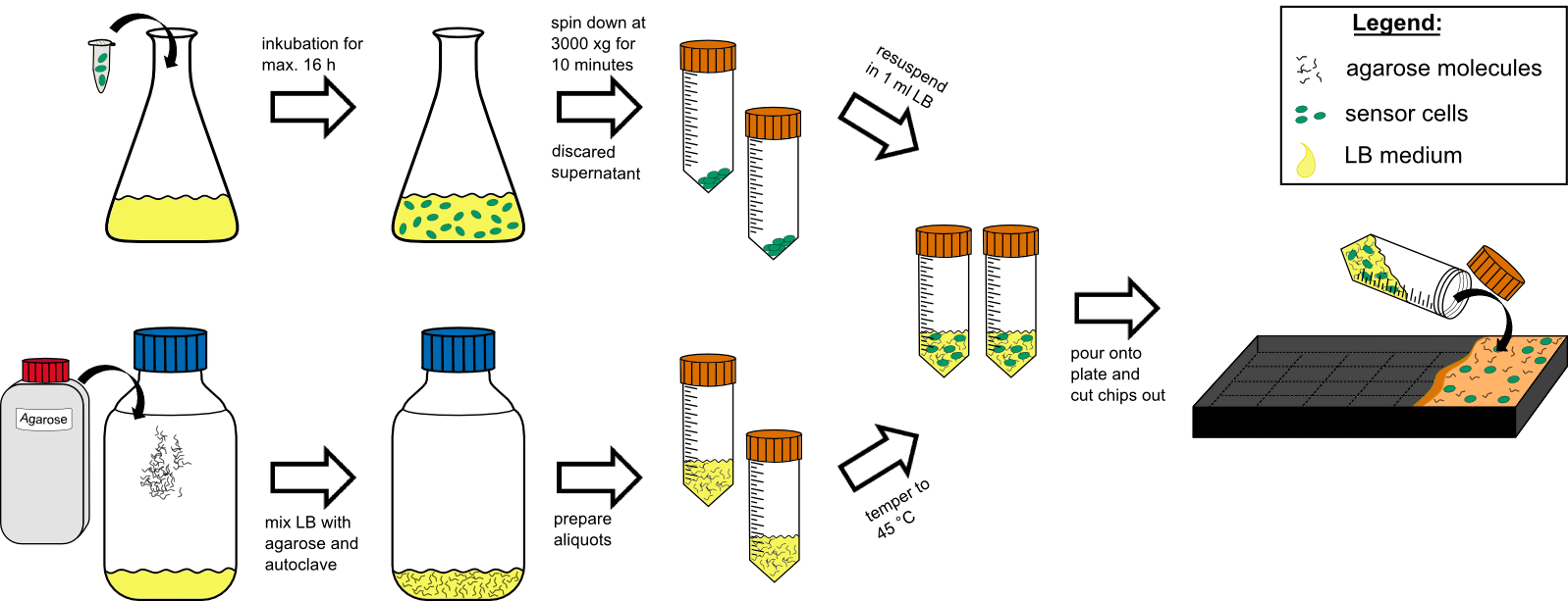
'''Cell Preparation''' | '''Cell Preparation''' | ||
| - | # over night culture of sensor cells (50 | + | # over night culture of sensor cells (50 ml in a 250 ml flask with) max. 16 h |
| - | # centrifuge all 50 | + | # centrifuge all 50 ml by 3000 g for 10 min at RT (21°C). |
# discard the supernatant | # discard the supernatant | ||
| - | # re-suspend the pellet in 1 mL tempered (~ | + | # re-suspend the pellet in 1 mL tempered (~21°C) LB-medium. |
'''Agar Preparation''' | '''Agar Preparation''' | ||
| - | # autoclave 50 | + | # autoclave 50 ml medium with 1.5%(w/v) agarose (has to be multiplied with the number of chips prepared). |
| - | # cool it down to | + | # cool it down to 45°C in a water bath. |
| Line 67: | Line 67: | ||
# mix the cooled medium with the cells by inverting gently. | # mix the cooled medium with the cells by inverting gently. | ||
| - | # pour it in the chip | + | # pour it in the chip mold, avoiding bubble formation (!). |
# wait for approximately 20 min until the agar has solidified. | # wait for approximately 20 min until the agar has solidified. | ||
# cut out the chips with a scalpel. | # cut out the chips with a scalpel. | ||
# put two chips into a labeled petri dish and store additional 4 chips in labeled petri dishs in the refrigerator. | # put two chips into a labeled petri dish and store additional 4 chips in labeled petri dishs in the refrigerator. | ||
| - | # incubate two chips for 1 h at | + | # incubate two chips for 1 h at 37°C prior to induction. |
| + | |||
<center> | <center> | ||
| - | {{Team:Aachen/Figure|Aachen 14-10-09 flowsheet chip manufacturingV8 ipo.png|title=Sensor-chip manufacturing|subtitle=Scheme illustrating the work flow during chip production.|width=1000px}} | + | {{Team:Aachen/Figure|Aachen 14-10-09 flowsheet chip manufacturingV8 ipo.png|title=Sensor-chip manufacturing|subtitle=Scheme illustrating the work flow during chip production. For the production steps see above.|width=1000px}} |
</center> | </center> | ||
| Line 81: | Line 82: | ||
For measurement of a fluorescence response in our sensor chips we used three different methods. | For measurement of a fluorescence response in our sensor chips we used three different methods. | ||
| - | '''First''', the Gel | + | '''First''', the '''Gel Doc™ XR+''' (BIO-RAD) was used, exciting with UV light for an exposure time of 1 s. |
| - | '''Second''', we used our own device [https://2014.igem.org/Team:Aachen/Project/Measurement_Device '''WatsOn'''] with blue light for excitation (450 or 480 nm) and special filters infront of the camera for selecting the appropriate emission spectrum. You can read even more about building your own WatsOn [https://2014.igem.org/Team:Aachen/Notebook/Engineering/WatsOn here]. | + | '''Second''', we used our own device [https://2014.igem.org/Team:Aachen/Project/Measurement_Device '''''WatsOn'''''] with blue light for excitation (450 or 480 nm) and special filters infront of the camera for selecting the appropriate emission spectrum. You can read even more about building your own ''WatsOn'' [https://2014.igem.org/Team:Aachen/Notebook/Engineering/WatsOn here]. |
| - | '''Third''', we used the | + | '''Third''', we used the '''Synergy Mx microplate reader''' (BioTek), putting the sensor chips into the lid of a common clear well plate. GFP was measured with an excitation of 496 ± 9 nm and an emission of 516 ± 9 nm and iLOV with an excitation of 450 ± 9 nm and emission of 495 ± 9 nm. |
<html> | <html> | ||
Latest revision as of 21:23, 17 October 2014
|
 "
"
