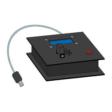
Team:Aachen/Notebook/Engineering/ODF
From 2014.igem.org
(→Technical Components) |
(→Saccharomyces cerevisiae) |
||
| (108 intermediate revisions not shown) | |||
| Line 4: | Line 4: | ||
= OD/F Device = | = OD/F Device = | ||
| - | On this page we present the technical details of our OD/F | + | On this page we present the technical details of our OD/F Device. You can skip to specific chapters by clicking on the panels below: |
| - | + | ||
<center> | <center> | ||
| - | <ul class=" | + | <html><ul class="team-grid" style="width:1064px;"> |
<!-- Overview --> | <!-- Overview --> | ||
| - | + | <li style="width:220px;margin-left: 23px;margin-right: 23px;margin-bottom: 23px;margin-top: 23px;"> | |
| - | + | <a href="https://2014.igem.org/Team:Aachen/Notebook/Engineering/ODF#dev" style="color:black"> | |
| - | <div class=" | + | <div class="team-item team-info" style="width:214px;height:214px;font-size: large;line-height:1.5em;"> |
| - | + | <br/><br> | |
| + | <b>General Considerations</b> | ||
| + | <br/><br/> | ||
</div> | </div> | ||
| - | </a> | + | <div class="team-item team-img" style="background: url(https://static.igem.org/mediawiki/2014/0/0f/Aachen_14-10-10_ODF_Button_ipo.png); norepeat scroll 0% 0% transparent; background-size:100%;width:214px;height:214px;"> </div></a> |
</li> | </li> | ||
| - | + | <li style="width:220px;margin-left: 23px;margin-right: 23px;margin-bottom: 23px;margin-top: 23px;"> | |
| - | + | <a href="https://2014.igem.org/Team:Aachen/Notebook/Engineering/ODF#od" style="color:black"> | |
| - | <div class=" | + | <div class="team-item team-info" style="width:214px;height:214px;font-size: large;line-height:1.5em;"> |
| - | + | <br/><br/> | |
| + | <b>OD Device</b> | ||
| + | <br/><br/> | ||
</div> | </div> | ||
| - | </a> | + | <div class="team-item team-img" style="background: url(https://static.igem.org/mediawiki/2014/0/04/Aachen_Cuvette_button_v1_ipo.png); norepeat scroll 0% 0% transparent; background-size:100%;width:214px;height:214px;"> </div></a> |
</li> | </li> | ||
| - | + | <li style="width:220px;margin-left: 23px;margin-right: 23px;margin-bottom: 23px;margin-top: 23px;"> | |
| - | + | <a href="https://2014.igem.org/Team:Aachen/Notebook/Engineering/ODF#f" style="color:black"> | |
| - | <div class=" | + | <div class="team-item team-info" style="width:214px;height:214px;font-size: large;line-height:1.5em;"> |
| - | + | <br/><br/> | |
| + | <b>F Device</b> | ||
| + | <br/><br/> | ||
</div> | </div> | ||
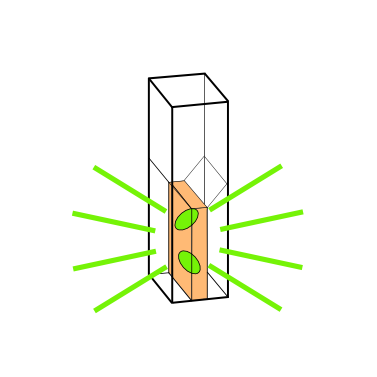
| - | </a> | + | <div class="team-item team-img" style="background: url(https://static.igem.org/mediawiki/2014/5/55/Aachen_17-10-14_Glowing_cuvette-ipo.png); norepeat scroll 0% 0% transparent; background-size:100%;width:214px;height:214px;"> </div></a> |
</li> | </li> | ||
| - | <li> | + | <li style="width:220px;margin-left: 23px;margin-right: 23px;margin-bottom: 23px;margin-top: 23px;"> |
| - | + | <a href="https://2014.igem.org/Team:Aachen/Notebook/Engineering/ODF#diy" style="color:black"> | |
| - | <div class=" | + | <div class="team-item team-info" style="width:214px;height:214px;font-size: large;line-height:1.5em;"> |
| - | + | <br/><br/> | |
| + | <b>DIY</b> | ||
| + | <br/><br/> | ||
</div> | </div> | ||
| - | </a> | + | <div class="team-item team-img" style="background: url(https://static.igem.org/mediawiki/2014/9/9e/Aachen_14-10-15_DIY_Cellocks_iNB.png); norepeat scroll 0% 0% transparent; background-size:100%;width:214px;height:214px;"> </div></a> |
</li> | </li> | ||
| - | |||
| - | |||
| - | |||
| - | |||
| - | |||
| - | |||
| - | |||
| - | |||
| - | |||
</ul> | </ul> | ||
</center> | </center> | ||
</html> | </html> | ||
| + | {{Team:Aachen/BlockSeparator}} | ||
| - | + | [[File:Aachen_14-10-10_ODF_Button_ipo.png|right|150px]] | |
| - | + | ||
= General Considerations = | = General Considerations = | ||
<span class="anchor" id="dev"></span> | <span class="anchor" id="dev"></span> | ||
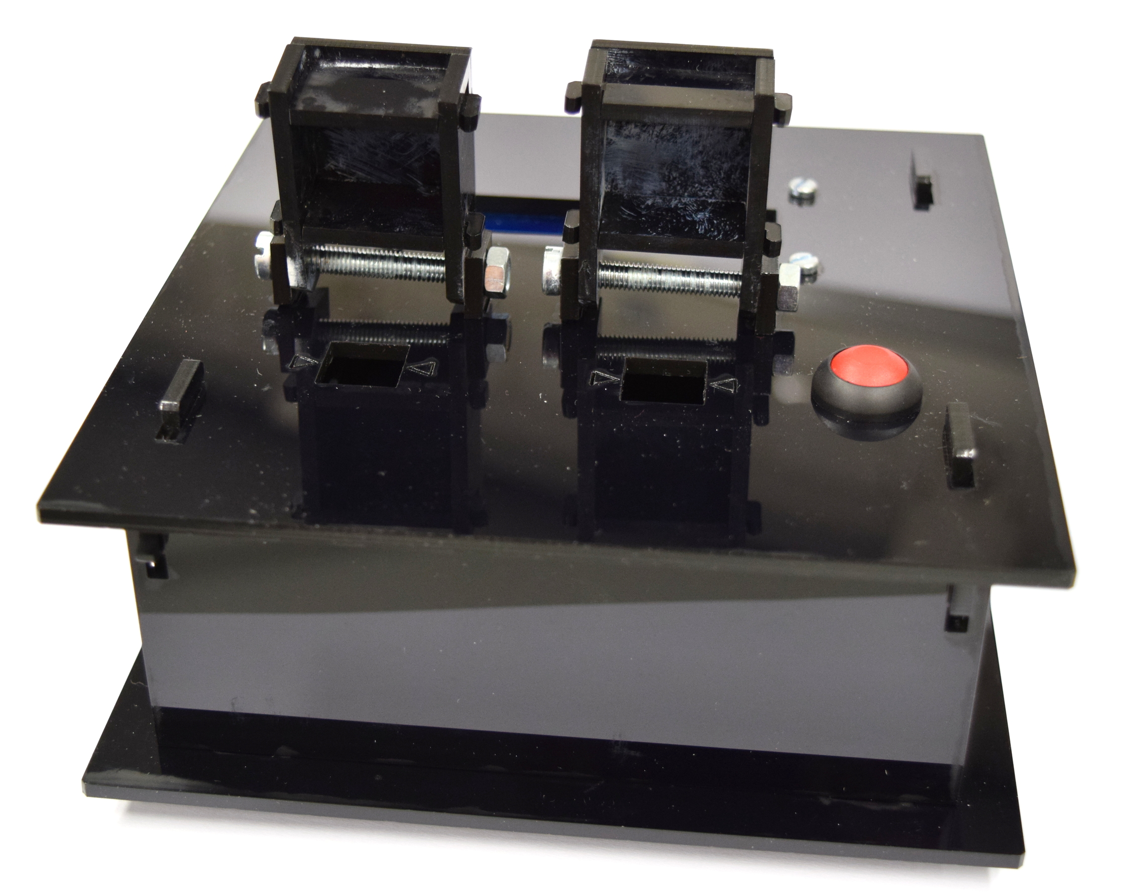
| - | + | Building the OD/F Device has been an interesting task. While this device has been developed mainly by the IT division of our team, we got an immense support from the biologists suffering from color-blindness, yet eager to help selecting the best color filters for the LEDs. | |
| - | + | ||
| - | + | ||
| - | + | ||
| - | + | ||
| - | + | ||
| - | + | ||
| - | + | ||
| - | + | ||
| - | + | ||
| - | The details about selecting filters, code and a construction manual | + | The measuring principle and guidelines for this project have already been presented in the [https://2014.igem.org/Team:Aachen/OD/F_device project] section. |
| + | Here, details about selecting filters, code and a construction manual are presented. | ||
=== Cuvette Holder === | === Cuvette Holder === | ||
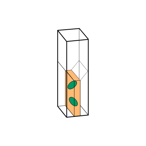
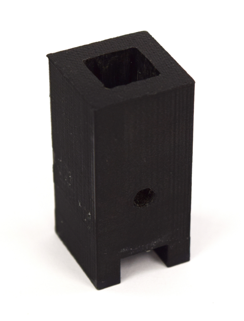
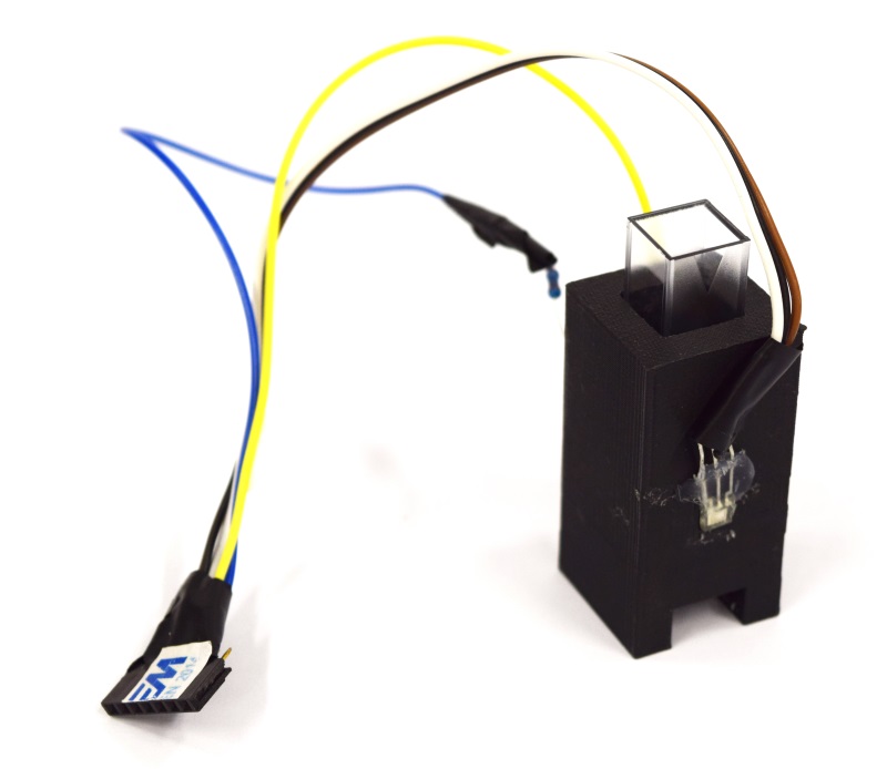
| - | The essential part of this device is the '''cuvette holder | + | The essential part of this device is the '''cuvette holder'''. In short, we had to overcome a dilemma created by the need for an optimal height for the sensor: |
* A too low sensor position bears problems with sedimentation as well as light diffraction from the bottom of the cuvette. | * A too low sensor position bears problems with sedimentation as well as light diffraction from the bottom of the cuvette. | ||
* The sensor has to be as close as possible to the bottom so that enough light shines through for the fluorescence measurement. | * The sensor has to be as close as possible to the bottom so that enough light shines through for the fluorescence measurement. | ||
| - | As a compromise, we place the sensor at a height of 0.75 cm | + | As a compromise, we place the sensor at a height of 0.75 cm. It is comparable to one of the standard heights (0.2 cm, 0.8 cm, 1.2 cm) of OD meters. It is important to note that our device works with filling volumens of just 1 mL, which in fact comes close to reality in the lab. |
The final cuvette holder design is rendered from a [https://2014.igem.org/Team:Aachen/Notebook/Engineering/Cuvette3D?action=raw stl-file] shown below: | The final cuvette holder design is rendered from a [https://2014.igem.org/Team:Aachen/Notebook/Engineering/Cuvette3D?action=raw stl-file] shown below: | ||
| Line 87: | Line 77: | ||
<iframe src="https://2014.igem.org/Team:Aachen/Notebook/Engineering/Cuvette3D?action=render | <iframe src="https://2014.igem.org/Team:Aachen/Notebook/Engineering/Cuvette3D?action=render | ||
" width=500px height=500px frameBorder="0"></iframe> | " width=500px height=500px frameBorder="0"></iframe> | ||
| + | <br/> | ||
| + | <b>Cuvette Holder developed for our OD/F Device.</b> | ||
</center> | </center> | ||
</html> | </html> | ||
| - | === Light | + | === Light Filters === |
| - | + | '''Finding the right and optimal filters is a tough challenge'''. | |
| + | The main goal throughout our project has been to choose easily available parts which are also inexpensive. Thus choosing Schott glasses as filters could not be considered. Alternatively, filters used for illumination of theaters were found to be an ideal solution. | ||
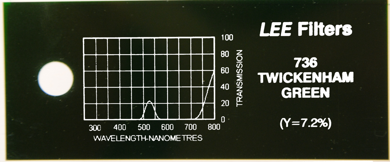
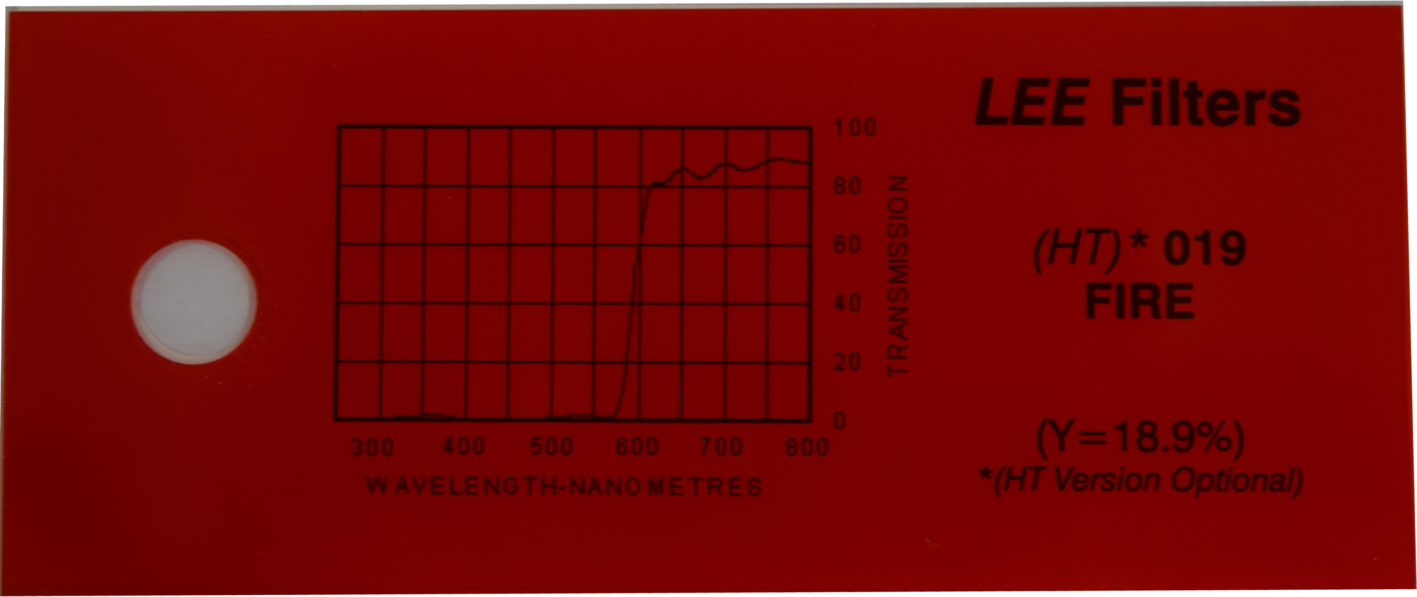
| - | + | We tested serveral filters and the optimal configuration of filters used is listed below. | |
| - | + | ||
| - | + | {| class="wikitable" | |
| - | + | ! Mode | |
| + | ! Fluorescence Protein | ||
| + | ! Filter Name | ||
| + | ! Filter | ||
| + | ! Peak Excitation | ||
| + | ! Peak Emission | ||
| + | |- | ||
| + | | Fluorescence | ||
| + | | [http://parts.igem.org/Part:BBa_E0040 GFPmut3b] | ||
| + | | [http://leefilters.com/lighting/colour-details.html#736 Twickenham Green] | ||
| + | | [[File:Aachen_Filter_736.png|200px]] | ||
| + | | 501nm | ||
| + | | 511nm | ||
| + | |- | ||
| + | | Optical Density | ||
| + | | -- | ||
| + | | [http://leefilters.com/lighting/colour-details.html#019 Fire] | ||
| + | | [[File:Aachen_Filter_019.png|200px]] | ||
| + | | 600nm | ||
| + | | 600nm | ||
| + | |} | ||
| - | + | The fluorescence protein [http://parts.igem.org/Part:BBa_E0040 GFPmut3b] has a peak excitation at 501 nm and a peak emission at 511 nm - too close together for our low-cost filters to block the excitation light but transmit the emitted light. Thus, we chose to excite at around 485 nm reduce false positive results below 500 nm. However, no adequate filter for these settings could be found. | |
| - | + | Eventually, using the dark greenish [http://leefilters.com/lighting/colour-details.html#736 Twickenham Green] filter only little amounts of light shorter than 500 nm gets through, reducing any bias from excitation illumination significantly. Unfortunately, the transmission rate of this filter is quite bad, 20% only, for the target emission wavelength of 511 nm. | |
| - | + | ||
| - | == Linearity == | + | == Linearity of the Hardware Light Sensor == |
<span class="anchor" id="lin"></span> | <span class="anchor" id="lin"></span> | ||
| - | |||
| - | |||
It is crucial that the selected hardware is mapping reality into the digital world of our $\mu$-Controller. | It is crucial that the selected hardware is mapping reality into the digital world of our $\mu$-Controller. | ||
In order to sense reality our setup uses a light to frequency sensor, [https://www.sparkfun.com/datasheets/Sensors/Imaging/TSL235R-LF.pdf TSL235R-LF]. | In order to sense reality our setup uses a light to frequency sensor, [https://www.sparkfun.com/datasheets/Sensors/Imaging/TSL235R-LF.pdf TSL235R-LF]. | ||
| Line 114: | Line 123: | ||
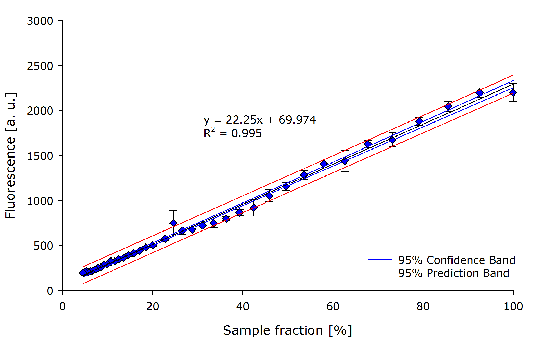
Using a dilution series of purified [https://2011.igem.org/Team:Glasgow/LOV2 iLOV] we could determine the characteristic curve for the light sensor. Finally we can conclude that the sensor is linear as expected and shown in the [https://www.sparkfun.com/datasheets/Sensors/Imaging/TSL235R-LF.pdf datasheet]. | Using a dilution series of purified [https://2011.igem.org/Team:Glasgow/LOV2 iLOV] we could determine the characteristic curve for the light sensor. Finally we can conclude that the sensor is linear as expected and shown in the [https://www.sparkfun.com/datasheets/Sensors/Imaging/TSL235R-LF.pdf datasheet]. | ||
| - | + | {{Team:Aachen/Figure|align=center|Aachen 15-10-14 Linearity iFG.PNG|title=Linearity of TSL235R-LF sensor|subtitle=Dilution series of GFP expressing ''E. coli'' showing linearity between fluorescence count and dilution. The linearity of the chosen sensor can be determined.|width=700px}} | |
| - | {{Team:Aachen/Figure|align=center| | + | |
| - | + | We are measuring optical density using our in-house developed cuvette holder. | |
| + | Particularly for optical density measurement, the amount of light shining through the sample is crucial. | ||
| + | If there is too few light, there will be not enough light registered at the sensor, and the resolution of the measurement shrinks. This should be prevented. | ||
| + | The chosen light to frequency sensor is reported to be very sensitive on the amount of light shining on it. | ||
| + | There are reports of the sensor breaking when put into [https://www.sparkfun.com/products/9768 sunlight on a nice day], and not being sensitive at both high light or low light [http://kesslerarduino.wordpress.com/author/kevinmkessler/page/2/ conditions]. | ||
| + | |||
{{Team:Aachen/BlockSeparator}} | {{Team:Aachen/BlockSeparator}} | ||
| + | [[File:Aachen_Cuvette_button_v1_ipo.png|right|150px]] | ||
| - | = | + | = Evaluation of the Optical Density Measurement = |
<span class="anchor" id="od"></span> | <span class="anchor" id="od"></span> | ||
| - | |||
=== From Transmittance to True Optical Density === | === From Transmittance to True Optical Density === | ||
At very low levels, uncorrected photometric determinations of cell densities show a decreasing proportionaility to actual cell density. | At very low levels, uncorrected photometric determinations of cell densities show a decreasing proportionaility to actual cell density. | ||
| - | This can also be observed using our | + | This can also be observed using our device. |
| - | In general, photometric determination of bacterial concentrations depends primarily on light scattering, rather than light absorption. Therefore | + | In general, photometric determination of bacterial concentrations depends primarily on light scattering, rather than light absorption. Therefore, often not absorption is measured, but transmittance. For this, the relationship between optical density (OD) and transmitted light $\frac{I_0}{I}$ exists as: |
$$ OD = \frac{I_0}{I} = \kappa \cdot c$$ | $$ OD = \frac{I_0}{I} = \kappa \cdot c$$ | ||
| + | |||
| + | where $I_0$ is the intensity of incoming light and $I$ the amount of the light passing through. | ||
However, this equation is linear only in a certain range. | However, this equation is linear only in a certain range. | ||
| Line 137: | Line 153: | ||
For our OD device we needed to correlate the transmittance measured by our sensor to an optical density anyway. | For our OD device we needed to correlate the transmittance measured by our sensor to an optical density anyway. | ||
| - | Our team members from the deterministic sciences emphasized on the correction method, which was conducted according to Lawrence and Maier | + | Our team members from the deterministic sciences emphasized on the correction method, which was conducted according to Lawrence and Maier (2006): |
* The relative density ($RD$) of each sample in a dilution series is calculated using $\frac{min(dilution)}{dilution}$. | * The relative density ($RD$) of each sample in a dilution series is calculated using $\frac{min(dilution)}{dilution}$. | ||
| Line 146: | Line 162: | ||
The derived function allows the conversion from transmission to optical density on our device and therefore calibrates our device. | The derived function allows the conversion from transmission to optical density on our device and therefore calibrates our device. | ||
| - | |||
| - | In our experiments, we find in accordance to | + | In our experiments, we find in accordance to Lawrence and Maier that the correction majorly depends on the technical equipment used, especially the LED, sensor and cuvettes. |
While this at first sight looks disappointing, it is also expected: | While this at first sight looks disappointing, it is also expected: | ||
Transmittance is the fraction of light not absorbed by some medium relative to the cell-free and clear medium. | Transmittance is the fraction of light not absorbed by some medium relative to the cell-free and clear medium. | ||
However, the transmittance is not only dependent on the amount of cells in the way of the light's beam, but also how much light shines through the cuvette in which fashion, and in which fraction is received by the sensor in which angles. | However, the transmittance is not only dependent on the amount of cells in the way of the light's beam, but also how much light shines through the cuvette in which fashion, and in which fraction is received by the sensor in which angles. | ||
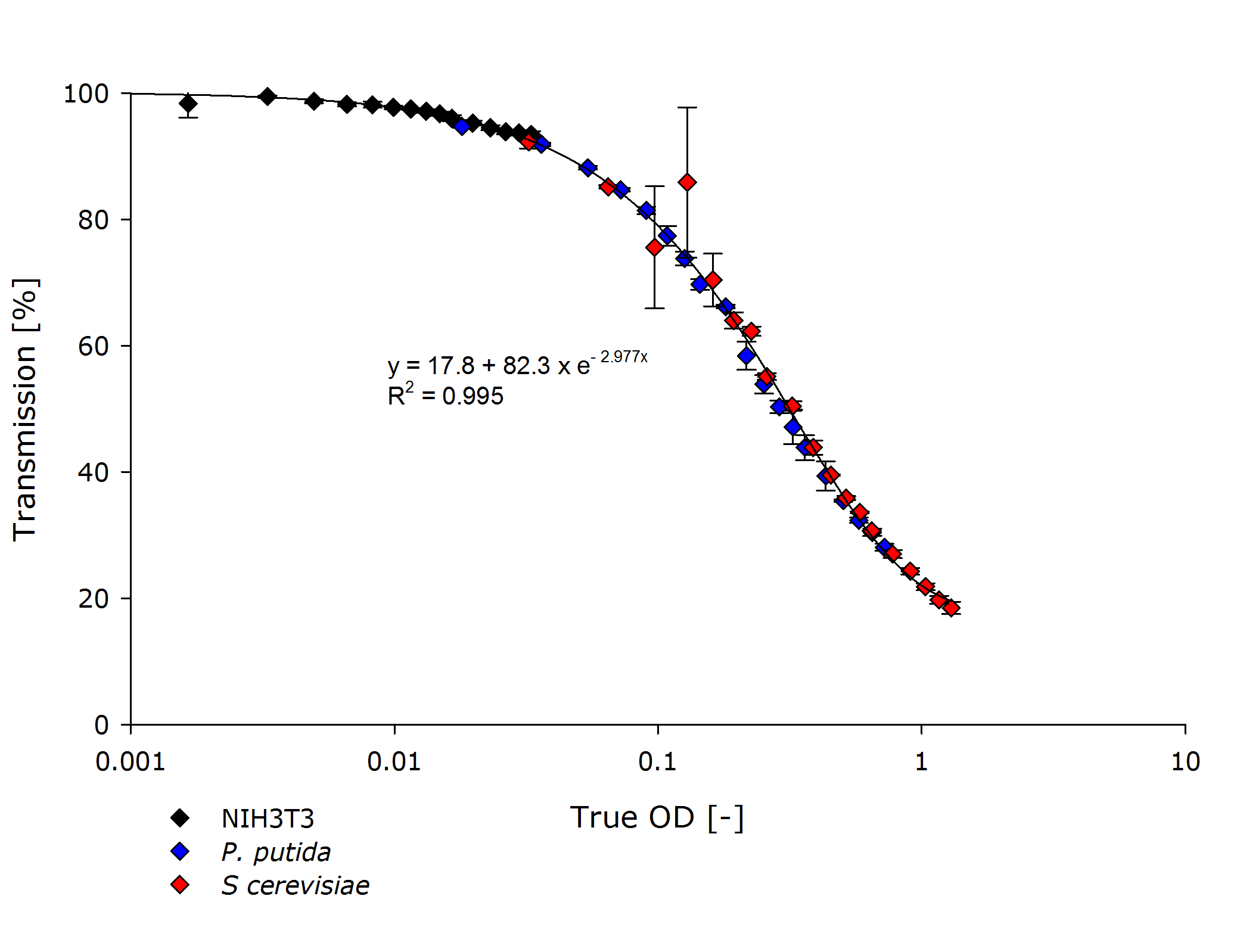
| - | Using the above formula we performed this experiment for Pseudomonas putida and Saccharomyces cerevisiae. | + | Using the above formula we performed this experiment for ''Pseudomonas putida'' and ''Saccharomyces cerevisiae'' and asked team [https://2014.igem.org/Team:Aachen/Collaborations/Freiburg Freiburg] to perform the same experiment using mamallian cells. |
| - | + | ||
| - | + | ||
=== Experiments === | === Experiments === | ||
| - | We performed several experiments during the development of the | + | We performed several experiments during the development of the device. |
| - | Finally we can relate the measured transmittance to the true Optical Density, and further, we can relate | + | Finally, we can relate the measured transmittance to the true Optical Density (true OD), and further, we can relate the true OD to the true OD of the photospectrometer in our lab. |
| - | By doing | + | By doing so, we can calibrate our device to meaningful values. |
| - | We have done this according to the previous section for Pseudomonas putida and Saccharomyces cerevisiae. | + | We have done this according to the previous section for ''Pseudomonas putida'' and ''Saccharomyces cerevisiae''. |
The final function for calculating the OD from the transmission calculated by our device can be calculated as | The final function for calculating the OD from the transmission calculated by our device can be calculated as | ||
| - | $$ OD = f(T) \circ g(device) $$ | + | $$ OD(T) = f(T) \circ g(device) $$ |
| - | where $f$ transforms transforms transmittance to true optical density for our device, and $g$ transforms true optical density of our device into the true optical density of the photospectrometer. This way our device is calibrated according to the photospectrometer. | + | where $f$ transforms transforms transmittance $T$ to true optical density for our device, and $g$ transforms true optical density of our device into the true optical density of the photospectrometer. This way our device is calibrated according to the photospectrometer. |
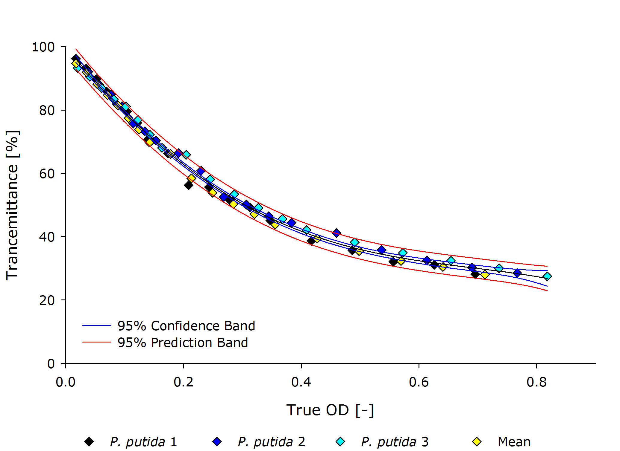
==== ''Pseudomonas putida'' ==== | ==== ''Pseudomonas putida'' ==== | ||
| - | + | ||
| - | {{Team:Aachen/Figure|align=center| | + | {{Team:Aachen/Figure|align=center|Aachen 15-10-14 Pputida iFG.PNG|title=True Optical Density to Transmittance plot for ''P. putida''|subtitle=|width=700px}} |
</center> | </center> | ||
<center> | <center> | ||
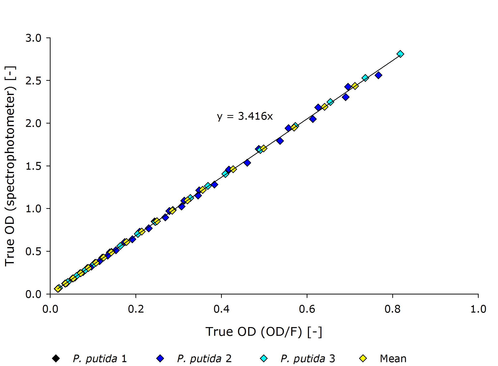
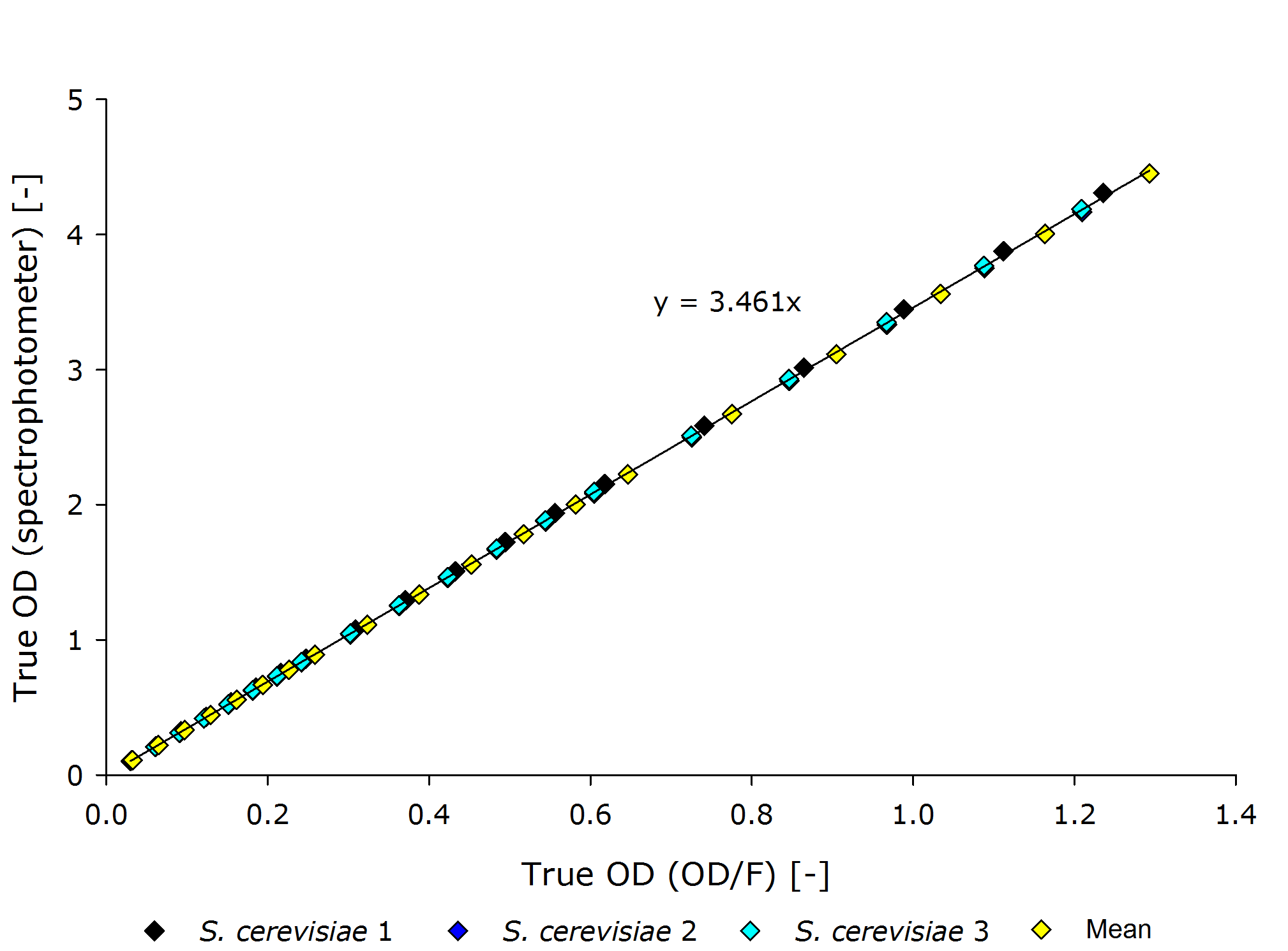
| - | {{Team:Aachen/Figure|align=center| | + | {{Team:Aachen/Figure|align=center|Aachen 15-10-14 Pputida OD iFG.PNG|title=Corrolating the true optical density of the OD/F Device to true optical density of the photospectrometer for ''P. putida''|subtitle=|width=700px}} |
</center> | </center> | ||
| Line 183: | Line 196: | ||
<center> | <center> | ||
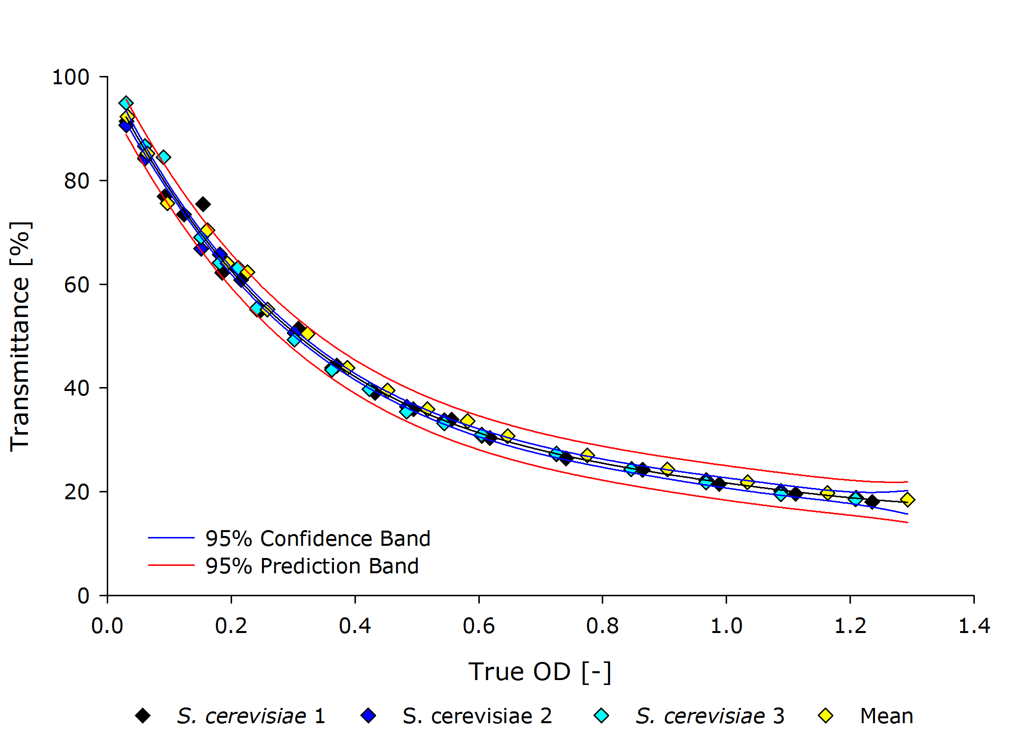
| - | {{Team:Aachen/Figure|align=center| | + | {{Team:Aachen/Figure|align=center|Aachen 15-10-14 Scer iFG.PNG|title=True Optical Density to Transmittance plot for ''S. cerivisiae''|subtitle=|width=700px}} |
</center> | </center> | ||
<center> | <center> | ||
| - | {{Team:Aachen/Figure|align=center| | + | {{Team:Aachen/Figure|align=center|Aachen 15-10-14 Scer OD iFG.PNG|title=Corrolating the true optical density of the OD/F Device to true optical density of the photospectrometer for ''S. cerivisiae''|subtitle=|width=700px}} |
</center> | </center> | ||
| - | From these plots it can | + | From these plots, it can be seen that our device delivers robust and reproducible results for both procaryotes and eucaryotes. |
| - | Also the function from transmittance to true | + | Also the function from transmittance to true OD follows a clear pattern, making its calculation possible on a low-end device like a microcontroller. |
| - | + | It is interesting to observer that function $g$, mapping the true OD of our device to the true OD of the photospectrometer, are close together for both ''P. putida'' and ''S. cerivisae'', as seen by the regression coefficient. | |
| - | Therefore we fix the regression coefficient for converting true OD of our device to true OD of the photospectrometer to 3.432 . | + | In fact, 3.416 and 3.461 are such close together, that the minor deviation could be just measuring inaccuracy. |
| + | Therefore, we fix the regression coefficient for converting true OD of our device to true OD of the photospectrometer to an average of 3.432 . | ||
| - | + | Additionally, the function $f$ for mapping transmittance to true OD for our device is similar for all cell types, as seen in the following figure. Therefore the exponential regression curve for all cell types specifies this function. | |
<center> | <center> | ||
| - | {{Team:Aachen/Figure| | + | {{Team:Aachen/Figure|Aachen_ODallstrains1.png|title=Transmission of different cell types at OD-values from 0.001-1|subtitle=The transmittance data of NIH 3T3 cells (mouse fibroblasts) align with the transmittance of ''P. putida'' and ''S. cerevisiae'' strains, even though the measured optical densities are lower by 1-2 orders of magnitude.|width=800px}} |
</center> | </center> | ||
| + | Finally, we have empirically determined our $OD(T)$ function by finding $f$ and $g$, such that we can convert true OD to the optical density of the photospectrometer. | ||
| + | |||
| + | By this evaluation, we have shown that our self-build OD/F Device can compete with commercial systems. | ||
| + | It is easy to calibrate by just calculating the true optical density. | ||
| - | |||
| - | |||
{{Team:Aachen/BlockSeparator}} | {{Team:Aachen/BlockSeparator}} | ||
| - | = | + | [[File:Aachen_17-10-14_Glowing_cuvette-ipo.png|right|150px]] |
| + | |||
| + | = Evaluation of the Fluorescence Measurement = | ||
<span class="anchor" id="f"></span> | <span class="anchor" id="f"></span> | ||
| - | |||
| - | |||
| - | |||
| - | |||
| - | |||
| - | |||
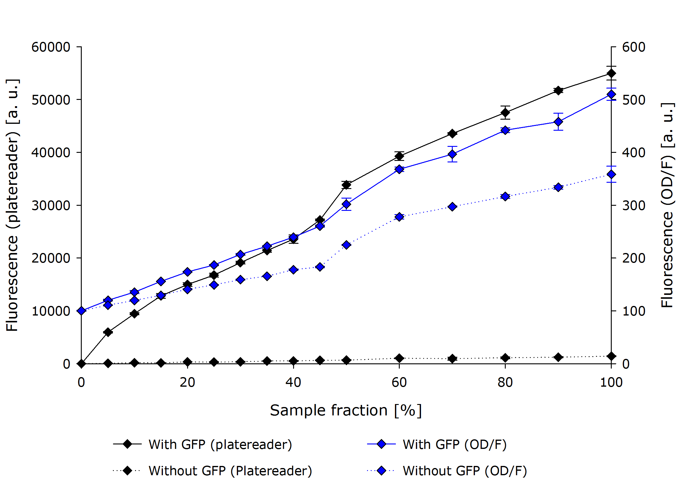
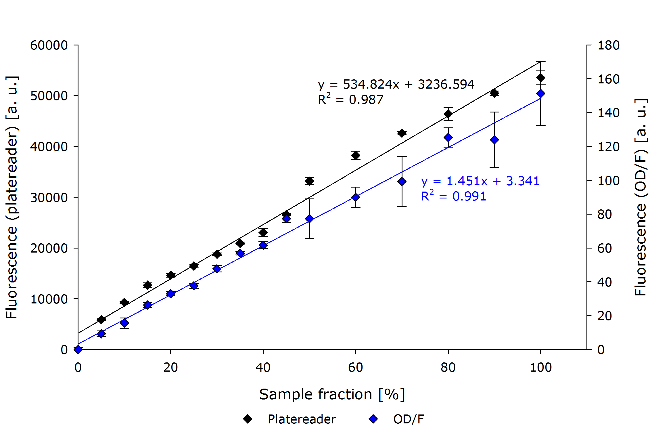
| - | For fluorescence measurement we | + | For the evaluation of the fluorescence measurement, we performed a dilution series of a constitutively GFPmut3b expressing ''E. coli''. |
| - | + | ||
| - | + | The below figure shows the absolute measurements for both the platereader and our OD/F Device. The abrupt jump at 50% concentration can be explained by a second dilution step and is prevalent in both devices. | |
| - | + | ||
It can be seen that the platereader show a much higher difference between the GFP and non-GFP cell culture at a higher standard deviation. | It can be seen that the platereader show a much higher difference between the GFP and non-GFP cell culture at a higher standard deviation. | ||
Another interesting metric is the difference between the GFP and non-GFP, which can be seen as the normalized fluorescence measure. | Another interesting metric is the difference between the GFP and non-GFP, which can be seen as the normalized fluorescence measure. | ||
<center> | <center> | ||
| - | {{Team:Aachen/Figure|align=center| | + | {{Team:Aachen/Figure|align=center|Aachn 15-10-14 F platereader ODF iFG.PNG|title=Fluorescence Measurement comparison OD/F Device and Platereader (absolute values)|subtitle=Comparison of a fluorescence measurement of our device and the platereader. Our OD/F Device shows no significant linearity.|width=700px}} |
</center> | </center> | ||
| - | If one compares the results there, as in | + | If one compares the results there, as in the below figure with normalized fluorescence values, interesting observations can be made. |
| - | First, both platereader and OD/F | + | First, both platereader and OD/F Device show very similar results. |
The regression curves differ only in a linear factor. | The regression curves differ only in a linear factor. | ||
| - | Most interestingly the general fit of the OD/F | + | Most interestingly the general fit of the OD/F Device to a linear function seems to be better than the platereader. |
Overall the linearity which has been observed earlier (in testing the general setup) could be verified. | Overall the linearity which has been observed earlier (in testing the general setup) could be verified. | ||
| - | Therefore our do-it-yourself OD/F | + | Therefore our do-it-yourself OD/F Device can be used to determine fluorescence. |
| - | + | ||
| - | + | ||
<center> | <center> | ||
| - | {{Team:Aachen/Figure|align=center| | + | {{Team:Aachen/Figure|align=center|Aachen 15-10-14 F platereader ODF2 iFG.PNG|title=Fluorescence Measurement comparison OD/F Device and platereader using normalized fluorescence values|subtitle=Comparison of a fluorescence measurement of our device and the platereader. Our OD/F Device shows no significant. A non-GFP expressing ''E. coli'' dilution has been used to normalize the GFP dilution series. A linear correlation can be seen.|width=700px}} |
</center> | </center> | ||
| + | |||
{{Team:Aachen/BlockSeparator}} | {{Team:Aachen/BlockSeparator}} | ||
| + | |||
| + | [[File:Aachen_14-10-15_DIY_Cellocks_iNB.png|right|150px]] | ||
= DIY: How to Build Your Own Device = | = DIY: How to Build Your Own Device = | ||
| Line 247: | Line 258: | ||
== Technical Components == | == Technical Components == | ||
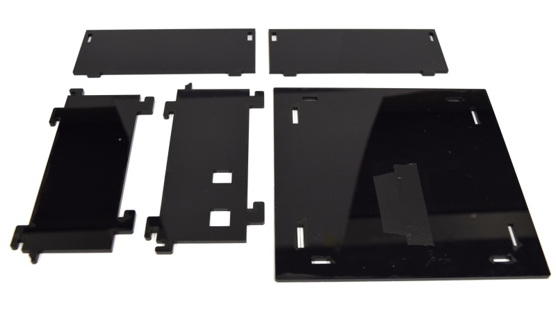
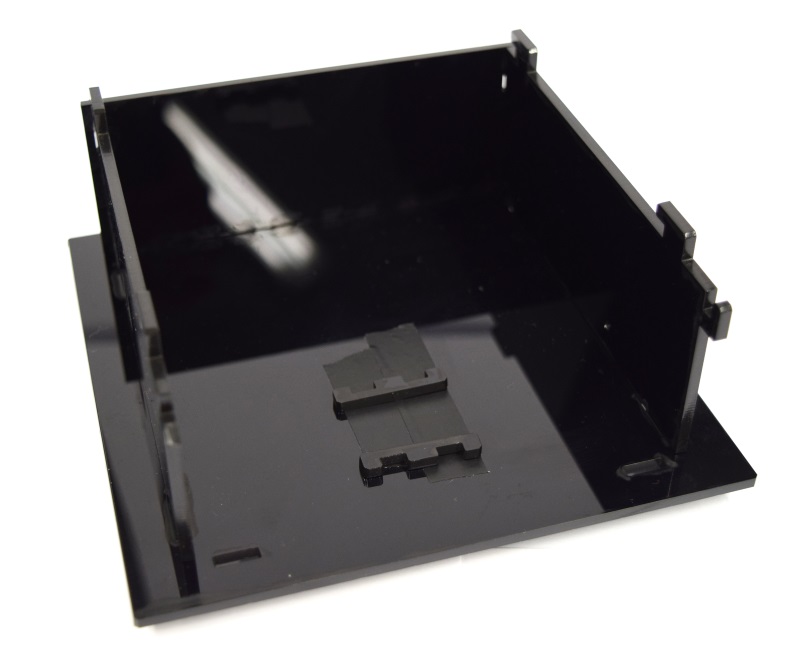
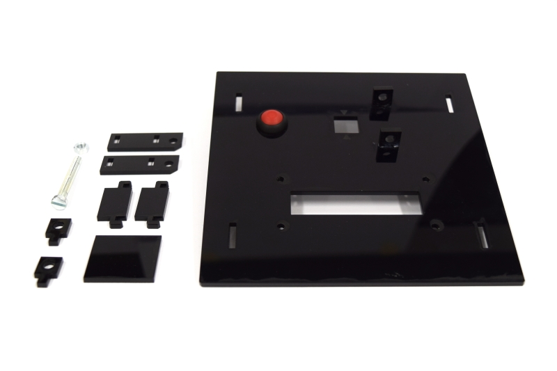
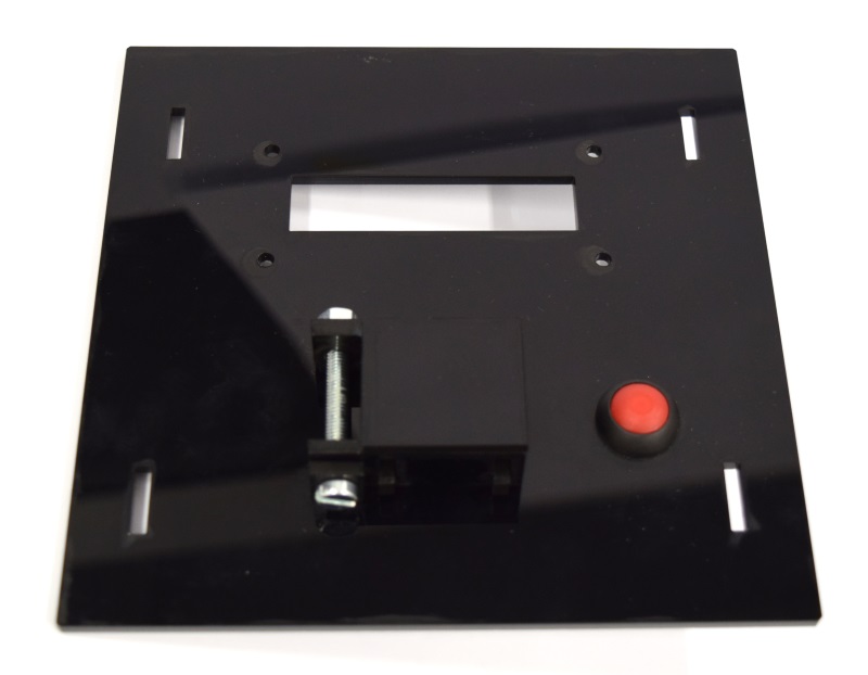
| - | While the casing and the cuvette holder are custom made, most of the parts are pre-made and | + | While the casing and the cuvette holder are custom made, most of the parts are pre-made and can be readily bought. The previous section lists all needed parts. |
| + | To get all these parts for creating your own OD/F Device is easy using the internet. Thus all '''potential customers have a market access''' to the used components. | ||
| - | Please find our custom parts for download below | + | Please find our custom parts for download below. Despite being custom parts, these are quite inenxpensive - so feel free to give our OD/F Device a test! For printing the 3D model of our cuvette holder and laser cutting our case, we want to express many thanks to [http://hci.rwth-aachen.de/fablab Fablab Aachen].<span class="anchor" id="ref2"></span> |
* cuvette holder [https://2014.igem.org/Template:Team:Aachen/cuvette.stl?action=raw STL file] | * cuvette holder [https://2014.igem.org/Template:Team:Aachen/cuvette.stl?action=raw STL file] | ||
| - | * casing single device [ SVG file] | + | * casing single device [https://static.igem.org/mediawiki/2014/b/bb/Aachen_ODF_device_casing.svg.zip SVG file] |
| - | * | + | * lid combined device [https://static.igem.org/mediawiki/2014/4/46/Aachen_Odf_device_combined_lid.svg.zip SVG file] |
| - | * Arduino Code for single device [https:// | + | * Arduino Code for single device [https://static.igem.org/mediawiki/2014/2/2f/Arduino_od_f_single.zip Sketchbook (.ino)] |
| - | * Arduino Code for combined device [https:// | + | * Arduino Code for combined device [https://static.igem.org/mediawiki/2014/e/e8/Arduino_odf_combined.zip Sketchbook (.ino)] |
You will need a special [http://www.exp-tech.de/images/product_images/description%20images/YWRobot/1602/LiquidCrystal_I2C1602V2.rar library] for the display, which can not be uploaded for legal reasons. | You will need a special [http://www.exp-tech.de/images/product_images/description%20images/YWRobot/1602/LiquidCrystal_I2C1602V2.rar library] for the display, which can not be uploaded for legal reasons. | ||
| - | ''' | + | <center> |
| + | '''All needed components their quantities and prices for creating your own OD/F Device''' | ||
{| class="wikitable" | {| class="wikitable" | ||
| - | ! align="center" |'''OD/F | + | ! align="center" |'''OD/F Device''' |
!! align="center" | | !! align="center" | | ||
!! align="center" |''' 1€=''' | !! align="center" |''' 1€=''' | ||
| Line 269: | Line 282: | ||
!! align="center" | | !! align="center" | | ||
|- | |- | ||
| - | ! Quantity!!Component!! Costs € !! Costs $ !! Final € !! Final $ | + | ! Quantity!!Component!! Costs [€] !! Costs [$] !! Final [€] !! Final [$] |
|- | |- | ||
| - | | 1||[http://www.dx.com/p/uno-r3-development-board-microcontroller-mega328p-atmega16u2-compat-for-arduino-blue-black-215600#.VDzwV9ysWBp Arduino UNO R3]|| | + | | 1||[http://www.dx.com/p/uno-r3-development-board-microcontroller-mega328p-atmega16u2-compat-for-arduino-blue-black-215600#.VDzwV9ysWBp Arduino UNO R3]||9.17||11.65||9.17||11.65 |
|- | |- | ||
| - | | 1||[http://www.mouser. | + | | 1||[http://www.mouser.de/ProductDetail/ams/TSL235R-LF/?qs=14HO7rLZPQsjmBHaoYCzkA%3D%3D TSL 235R]||2.47||3.14||2.47||3.14 |
|- | |- | ||
| - | | 1||[http://www.dx.com/p/16-x-2-character-lcd-display-module-with-blue-backlight-121356 | + | | 1||[http://www.dx.com/p/16-x-2-character-lcd-display-module-with-blue-backlight-121356 Display 16x2]||2.58||3.28||2.58||3.28 |
|- | |- | ||
| - | | 1||[http://www.dx.com/p/lcd1602-adapter-board-w-iic-i2c-interface-black-works-with-official-arduino-boards-216865#.VDzxHNysWBp LCD Display to I2C]|| | + | | 1||[http://www.dx.com/p/lcd1602-adapter-board-w-iic-i2c-interface-black-works-with-official-arduino-boards-216865#.VDzxHNysWBp LCD Display to I2C]||1.57||1.99||1.57||1.99 |
|- | |- | ||
| - | | 1||[http://www.newark.com/multicomp/mcpas6b1m1ce3/switch-pushbutton-spst-400ma-125v/dp/12P7696?ost=1638329 Pushbutton]|| | + | | 1||[http://www.newark.com/multicomp/mcpas6b1m1ce3/switch-pushbutton-spst-400ma-125v/dp/12P7696?ost=1638329 Pushbutton]||2.90||3.69||2.90||3.69 |
|- | |- | ||
| - | | 1||[http://shop.leefiltersusa.com/Swatch-Book-Designers-Edition-SWB.htm filter leaflet]|| | + | | 1||[http://shop.leefiltersusa.com/Swatch-Book-Designers-Edition-SWB.htm filter leaflet]||1.57||2.00||1.57||2.00 |
|- | |- | ||
| - | | 20||[http://www.dx.com/p/diy-male-to-female-dupont-breadboard-jumper-wires-black-multi-color-40-pcs-10cm-339078#.VDzxSdysWBp jumper wire cables]|| | + | | 20||[http://www.dx.com/p/diy-male-to-female-dupont-breadboard-jumper-wires-black-multi-color-40-pcs-10cm-339078#.VDzxSdysWBp jumper wire cables]||0.09||0.11||1.80||2.28 |
|- | |- | ||
| - | | 1||[http://www.dx.com/p/syb-170-mini-breadboard-for-diy-project-red-140101#.VDzyudysWBo small breadboard]|| | + | | 1||[http://www.dx.com/p/syb-170-mini-breadboard-for-diy-project-red-140101#.VDzyudysWBo small breadboard]||1.98||2.51||1.98||2.51 |
|- | |- | ||
| - | | 1||[http://www.dx.com/p/universal-ac-charger-w-dual-usb-output-for-iphone-ipad-ipod-white-us-plug-244893 | + | | 1||[http://www.dx.com/p/universal-ac-charger-w-dual-usb-output-for-iphone-ipad-ipod-white-us-plug-244893 power supply]||2.20||2.80||2.20||2.80 |
|- | |- | ||
| - | | 1||cuvette holder (3D print service of your choice)|| 6.44 | + | | 1||cuvette holder (3D print service of your choice)||6.44||8.18||6.44||8.18 |
|- | |- | ||
| - | | 1||3 mm acrylic glas (black)|| 7.98 | + | | 1||3 mm acrylic glas (black)||7.98||10.14||7.98||10.14 |
|- | |- | ||
| - | | 1||[http://www.dx.com/p/prototype-universal-printed-circuit-board-breadboard-golden-10-piece-pack-143913 | + | | 1||[http://www.dx.com/p/prototype-universal-printed-circuit-board-breadboard-golden-10-piece-pack-143913 Prototype Universal Printed Circuit Board]||2.27||2.88||2.27||2.88 |
|- | |- | ||
| - | | 1||[http://www.dx.com/p/2-54mm-1x40-pin-breakaway-straight-male-header-10-piece-pack-144191#. | + | | 1||[http://www.dx.com/p/2-54mm-1x40-pin-breakaway-straight-male-header-10-piece-pack-144191#.VEGRF2d_tGg Male Headers]||2.14||2.72||2.14||2.72 |
| + | |- style="border-top: 2px solid #808080;" | ||
| + | | 1||[http://www.mouser.de/ProductDetail/Dialight/550-2505F/?qs=0KZIkTEbAAvqMAW7suDOXg== LED 600 nm]||0.94||1.19||0.94||1.19 | ||
|- | |- | ||
| - | + | ! -!!Total OD!!-!!-!! 46.01 !! 58.45 | |
|- | |- | ||
| - | | 1||[http://www. | + | | 1||[http://www.leds.de/Low-Mid-Power-LEDs/SuperFlux-LEDs/Nichia-Superflux-LED-blau-3lm-100-NSPBR70BSS.html LED 480 nm]||0.99||1.26||0.99||1.26 |
|- | |- | ||
| - | ! | + | ! -!!Total F!!-!!-!! 46.06 !! 58.52 |
| + | |- style="border-top: 2px solid #808080;;" | ||
| + | | 1||[http://www.mouser.de/ProductDetail/Dialight/550-2505F/?qs=0KZIkTEbAAvqMAW7suDOXg== LED 600nm]||0.94||1.19||0.94||1.19 | ||
|- | |- | ||
| - | | 1||[http://www.leds.de/Low-Mid-Power-LEDs/SuperFlux-LEDs/Nichia-Superflux-LED-blau-3lm-100-NSPBR70BSS.html LED | + | | 1||[http://www.leds.de/Low-Mid-Power-LEDs/SuperFlux-LEDs/Nichia-Superflux-LED-blau-3lm-100-NSPBR70BSS.html LED 480 nm]||0.99||1.26||0.99||1.26 |
|- | |- | ||
| - | + | | 1||cuvette holder (3D print service of your choice)||6.44||8.18||6.44||8.18 | |
|- | |- | ||
| - | + | ! -!!Total OD/F!!-!!-!! 53.44 !! 67.89 | |
| - | + | ||
| - | + | ||
| - | + | ||
| - | ! Total OD/F !!!!!! | + | |
|- | |- | ||
|} | |} | ||
| + | </center> | ||
| - | For more detailed economical information about the OD/F project visit our [https://2014.igem.org/Team:Aachen/PolicyPractices/Economics | + | For more detailed economical information about the OD/F project visit our [https://2014.igem.org/Team:Aachen/PolicyPractices/Economics Economical View] page. |
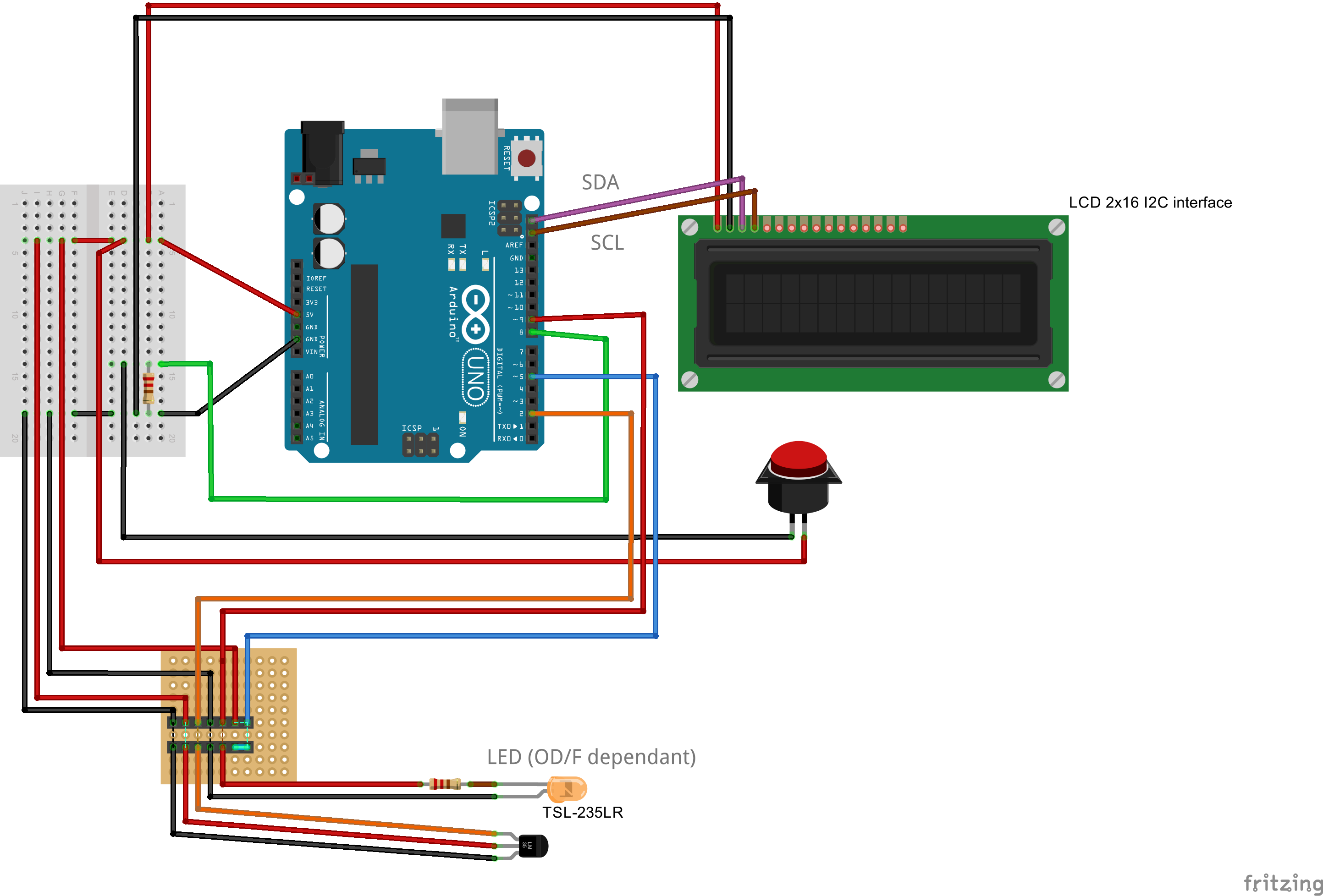
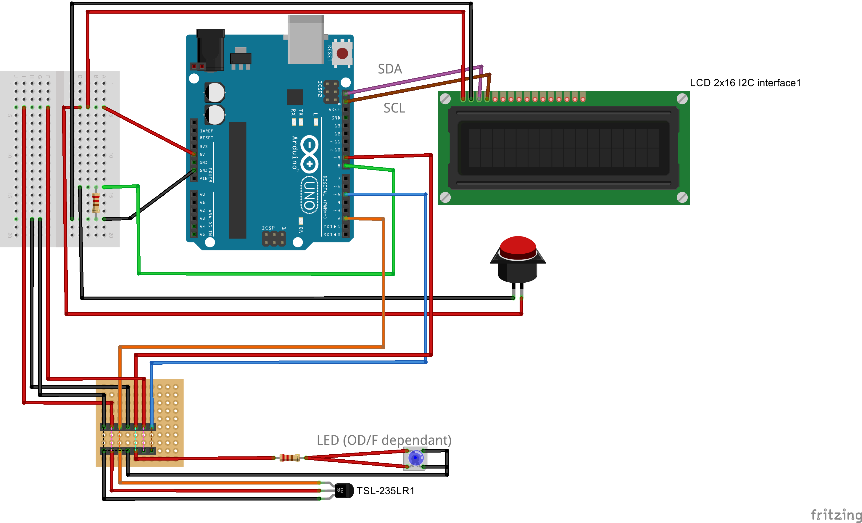
== Breadboards == | == Breadboards == | ||
| Line 338: | Line 352: | ||
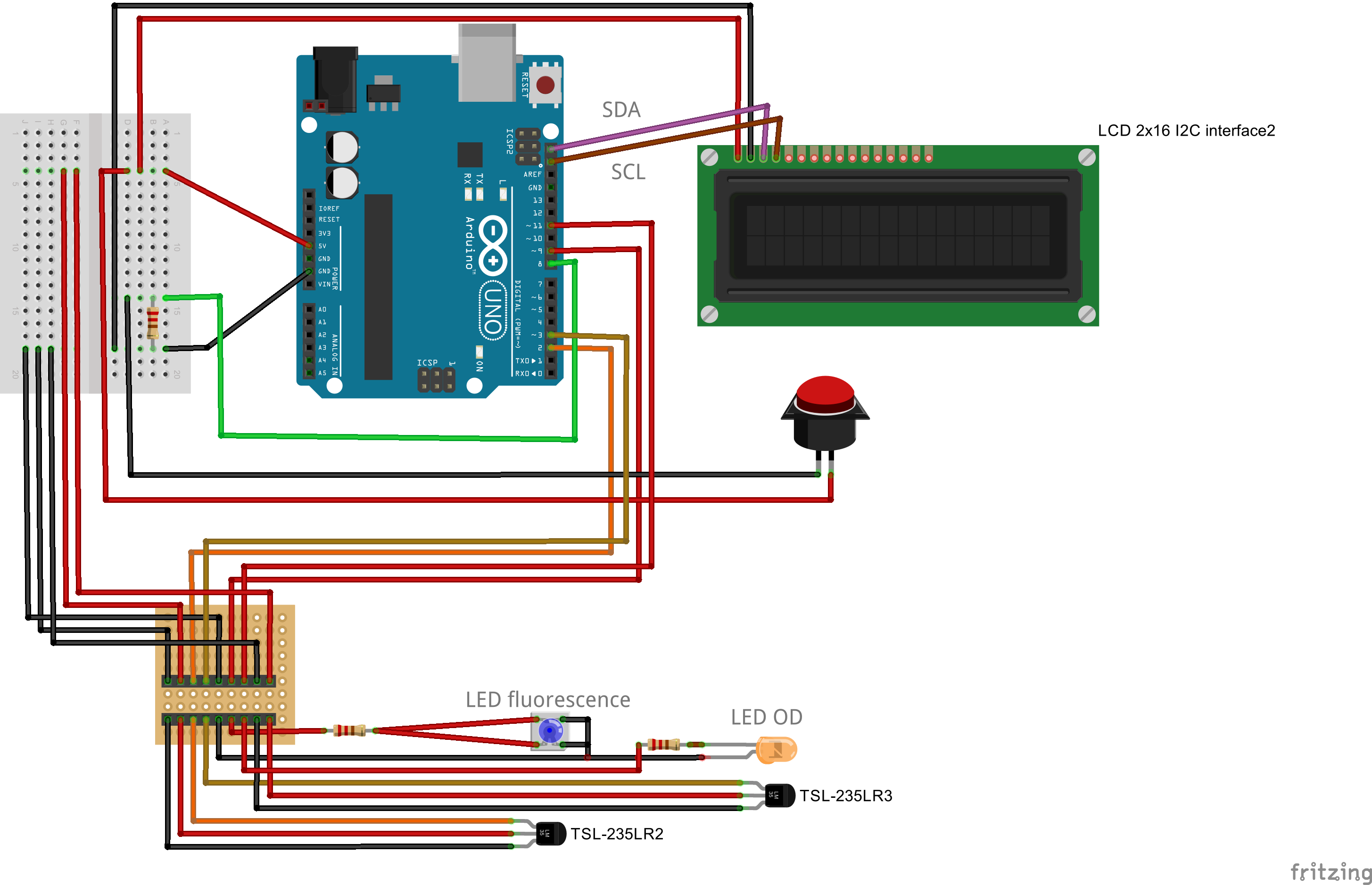
All you need to do is choosing another lid, and connect a second light to frequency sensor to your Arduino. | All you need to do is choosing another lid, and connect a second light to frequency sensor to your Arduino. | ||
Right at the bottom we present you the differences in wiring things up. | Right at the bottom we present you the differences in wiring things up. | ||
| - | Building the combined device is straight forward and very similar to the single device. You will need a slightly larger connector, a different lid for your case, and | + | Building the combined device is straight forward and very similar to the single device. You will need a slightly larger connector, a different lid for your case, and some more cables. The corresponding fritzing-layout is presented below. |
{{Team:Aachen/Figure|Aachen_ODF_combined_Steckplatine.png|align=center|title=Our novel biosensor approach|subtitle=Expression of the TEV protease is induced by HSL. The protease cleaves the GFP-REACh fusion protein to elecit a fluorescence response.|width=900px}} | {{Team:Aachen/Figure|Aachen_ODF_combined_Steckplatine.png|align=center|title=Our novel biosensor approach|subtitle=Expression of the TEV protease is induced by HSL. The protease cleaves the GFP-REACh fusion protein to elecit a fluorescence response.|width=900px}} | ||
| Line 357: | Line 371: | ||
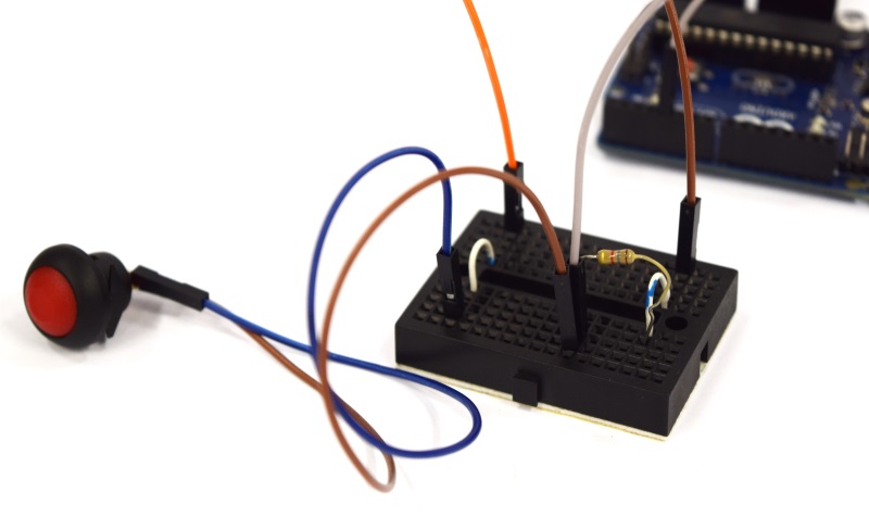
| [[File:Aachen_ODF_12.JPG|300px]] || Your final assembly should then look like this. Now place the correct filter into the cuvette holder, directly in front of the sensor. Make sure that the filter does not degrade due to the glue! | | [[File:Aachen_ODF_12.JPG|300px]] || Your final assembly should then look like this. Now place the correct filter into the cuvette holder, directly in front of the sensor. Make sure that the filter does not degrade due to the glue! | ||
|- | |- | ||
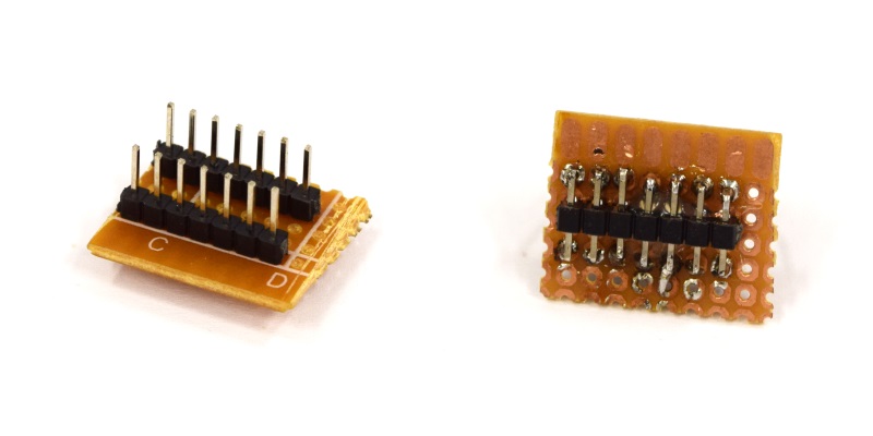
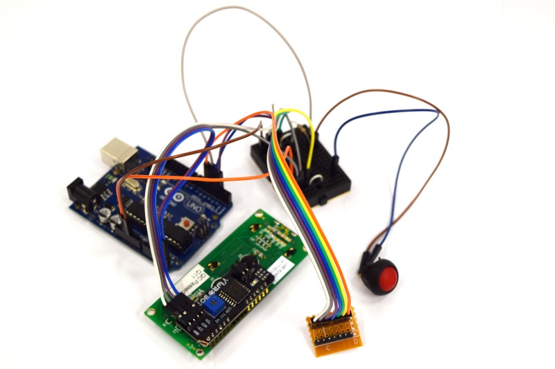
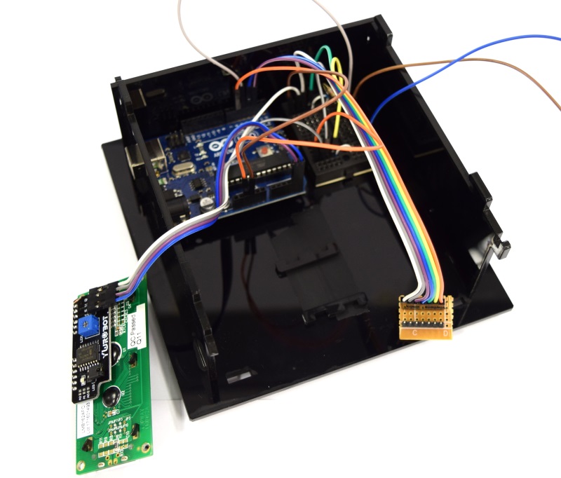
| - | | [[File:Aachen_ODF_14.JPG|300px]] || As the case can be used for both, fluorescence and OD measurement, we use a combined plug. Just three header rows (7 pins) and connect them as we did. | + | | [[File:Aachen_ODF_14.JPG|300px]] || As the case can be used for both, fluorescence and OD measurement, we use a combined plug. Just three header rows (7 pins, 9pins for combined) and connect them as we did. |
|- | |- | ||
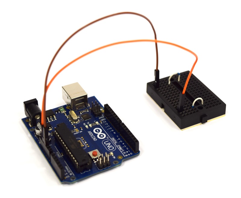
| [[File:Aachen_ODF_1.JPG|300px]] || Now we're doing the wiring. Connect the Arduino 5V and GND such that you have one 5V and one GND line on your breadboard. | | [[File:Aachen_ODF_1.JPG|300px]] || Now we're doing the wiring. Connect the Arduino 5V and GND such that you have one 5V and one GND line on your breadboard. | ||
| Line 367: | Line 381: | ||
| [[File:Aachen_ODF_6.JPG|300px]] || ... also place the cuvette holder into the device. Attach the display to the device lid and close the casing. | | [[File:Aachen_ODF_6.JPG|300px]] || ... also place the cuvette holder into the device. Attach the display to the device lid and close the casing. | ||
|- | |- | ||
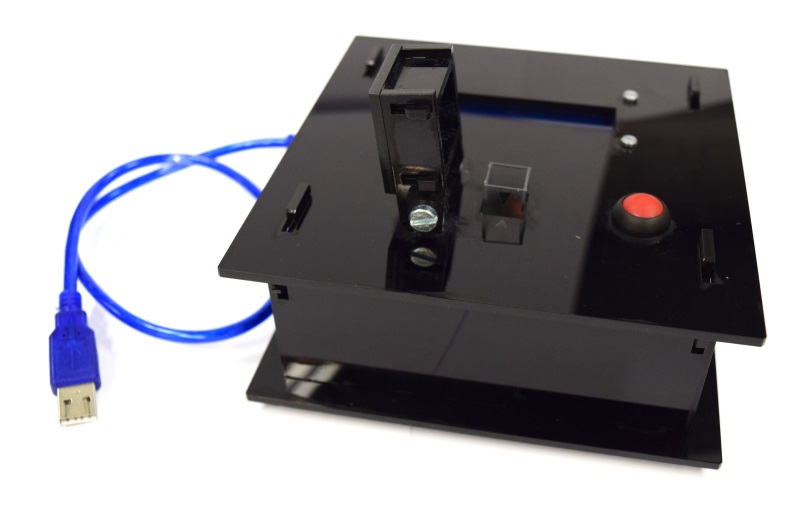
| - | | [[File:Aachen_ODF_7.JPG|300px]] || Congratulations! You have finished constructing your own OD/F device! | + | | [[File:Aachen_ODF_7.JPG|300px]] || Congratulations! You have finished constructing your own OD/F Device! |
| + | |- | ||
| + | | [[File:Aachen_zwei_Kuevetten.jpg|300px]] || ... or even the combined device! | ||
|} | |} | ||
| + | |||
| + | {{Team:Aachen/BlockSeparator}} | ||
| + | |||
| + | == References == | ||
| + | Lawrence, J. V., & Maier, S. (1977). Correction for the inherent error in optical density readings. Applied and Environmental Microbiology, 33(2), 482–484. Available at: http://www.pubmedcentral.nih.gov/articlerender.fcgi?artid=170707&tool=pmcentrez&rendertype=abstract. | ||
{{Team:Aachen/Footer}} | {{Team:Aachen/Footer}} | ||
Latest revision as of 03:45, 18 October 2014
|
|
|
|
|
 "
"
