Team:Heidelberg/pages/Linker Software
From 2014.igem.org
(→General procedure) |
(→Step 1) |
||
| Line 58: | Line 58: | ||
For this, we took into account the fact that proteins have some flexible amino acids at their extremities. This flexible part may come from the protein itself, but also from the 2 glycines that are included at the N-terminal part and from the extein at the C-terminal part. Those two latter parts comes from our linkers. Those parts have no preferential angles and offers a large amount of possibilities to insert fitting linkers. But this flexibility is also a drawback as we have to include this large amount of possible angles and length to our path search. | For this, we took into account the fact that proteins have some flexible amino acids at their extremities. This flexible part may come from the protein itself, but also from the 2 glycines that are included at the N-terminal part and from the extein at the C-terminal part. Those two latter parts comes from our linkers. Those parts have no preferential angles and offers a large amount of possibilities to insert fitting linkers. But this flexibility is also a drawback as we have to include this large amount of possible angles and length to our path search. | ||
In this first step, the software explicitely takes these flexible parts into account to check for the possibility of straight linkers. As the angles and the length of the flexible parts are variable, the software position their extremity on a sphere centered on the last fixed position of the structure as explained above. The radius of this sphere is incremented in a discrete manner, in 4 steps, from 5.25 Å to the maximum length of the flexible part. | In this first step, the software explicitely takes these flexible parts into account to check for the possibility of straight linkers. As the angles and the length of the flexible parts are variable, the software position their extremity on a sphere centered on the last fixed position of the structure as explained above. The radius of this sphere is incremented in a discrete manner, in 4 steps, from 5.25 Å to the maximum length of the flexible part. | ||
| - | Then all possible straight segments between the points and the lastpoints are tested. If they are closer than 5 Å to the protein, of if they cross it, then they are rejected. If they are kept, then the software checks whether the length of the segments is compatible with the feasible alpha helices in terms of length: if the length of a given segment equal one of the 8 alpha helix lengths plus or minus 0.75 Å, then the path is eventually saved. | + | Then all possible straight segments between the points and the lastpoints are tested. If they are closer than 5 Å to the protein, of if they cross it, then they are rejected. If they are kept, then the software checks whether the length of the segments is compatible with the feasible alpha helices in terms of length: if the length of a given segment equal one of the 8 alpha helix lengths plus or minus 0.75 Å, then the path is eventually saved. |
===Step 2=== | ===Step 2=== | ||
Revision as of 02:21, 18 October 2014
Contents |
Abstract
As already introduced, artificially circularized proteins may gain some heat stability by restraining the C- and N-terminus from moving around freely. This circularization may be trivial when the protein termini are very close to each other, which seems to be reasonably common [1]. However, if the ends are too far from each other, a long linker is needed to connect them. This linker should not change the natural conformation of the protein and should constrain the relative position of the ends to restrict the degrees of freedom and thus to stabilize the structure even when heated up. On top, these linkers should not affect any of the protein functions. Consequently it is important to prevent linkers from passing through the active site or from covering binding domains to other molecules for example. Therefore one needs to be able to define the shape of possible linkers. This section describes the software we developed to design such linkers. We would like to stress that this work has been made possible thanks to the feedback between computer modeling and experimental work: We could first design linkers in silico, test them experimentally and use the results to further calibrate the software. To our knowledge, this is the first time that such an approach is used to customly design rigid linkers with angles to connect protein extremities.
General procedure
In short, the software can provide a weighted list of linkers to circularize any protein of interest with a known structure. Those linkers are made of rigid alpha helices segments connected with defined angles. Contrary to flexible linkers, those rigid linkers were expected to constrain the protein extremities and to confer better heat stability. Such an idea was already developed [2] but only with alpha helices defining simple rods, and without any possibility to introduce angles. To generate those linkers, we first defined the geometrical paths, with segments and angles, that they should follow. The geometrical paths that are biologically feasible are afterwards translated into amino acid sequences. Both the compatibility of paths with possible structures and the translation were made possible thanks to our modeling approaches. The first approach consisted in performing a statistical analysis of more than 17000 known non-homologous structures containing alpha helices connected with angles. For the second approach, we modeled the conformation of linkers circularizing proteins of known structure and analyzed them for certain properties. This second approach was run for a large number of proteins thanks to our distributing computing system igemathome. The software provides different possible linkers with weights that provide the ranking of the linkers depending on their capacity to maintain protein activity at higher temperatures. They were generated thanks to an extensive linker screening on the target protein lambda-lysozyme, using the first modeling approach. The documentation of our CRAUT software can be found here.
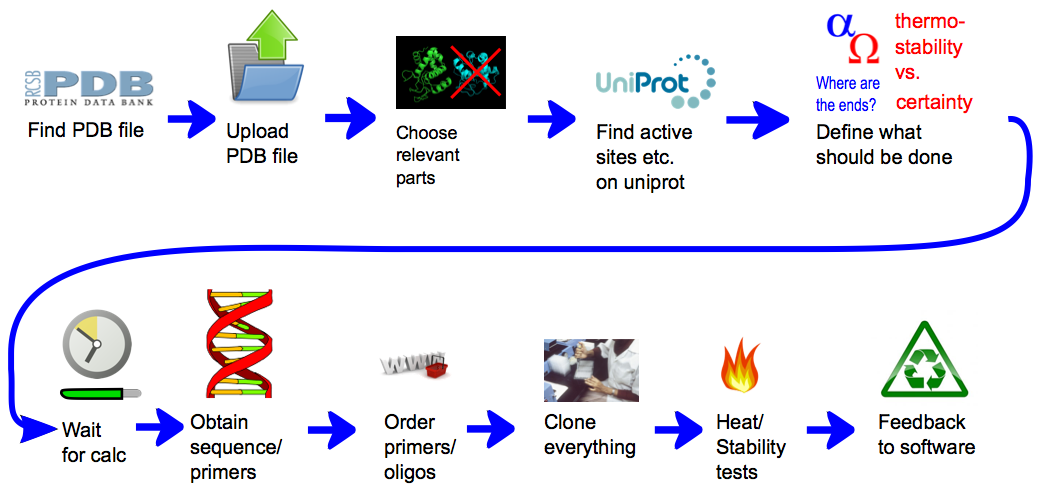
A representation of the general concept of CRAUT. At first the user provides it with a protein structure, by providing it with a PDB file. Then he can add relevant data, like binding sites, that he has found in databases. Then he chooses which parts of the protein the software should circularize and which parts of the protein should be ignored. After the calculations have finished, the user gets a sequence of the best linker, with which he could circularize the target protein.
Background
Classically, protein linkers were designed in three different manners. The easiest way is to define the length that a linker should cover and then simply use a flexible glycine-serine peptide with the right amount of amino acids to match this length. Glycine is used for flexibility, as it has no sidechain and does not produce any steric hindrance, while serine is used for solubility, as it has a small polar side chain. This solubility is important, as the linkers should not pass through the hydrophobic core of the protein, but should be dissolved in the surrounding medium. These flexible linkers were normally used for circularization but also for connecting different proteins, when the main goal is that the different parts are connected, but not how they are connected, or when the flexiblity of the linker was required for specific applications.
A second strategy consists in using rigid helical linkers to keep proteins or protein domains at a certain distance from each other. This is especially important for signalling proteins and fluorescent proteins. One major property of alpha helices is that they always fold in a defined way with well defined angles and lengths. There are also many different helical patterns that differ in stability and solubility. Although they have been used to design cirularizing linkers [2]. One big disadvantage of this strategy is that one can only build straight linkers with helices. So in the context of circularization, if an artificial line that would connect protein extremities is crossing the protein, this strategy is not an option.
The third option, which served as a base to develop our approach and which came from discussions with the group of Rebecca Wade in Heidelberg, Germany, consists in designing customly tailored linkers for each specific application. These linkers can be obtained from protein structure prediction. At first one needs to define the path that the linker should take to connect the protein ends. Afterwards, one designs a possible linker sequence that might fit well. Next one makes a structure prediction of the linker attached to the proteins to validate the prediction. Several different linkers, with slight changes, can be compared. This is repeated several times until the linker effectively follows the expected path. This method requires a strong knowledge on protein folding and protein structure prediction and is computationaly intensive. On the other hand, the benefit can be important as the interaction of the linker with the protein surface can be taken into account and as one can accurately define the path taken by the linker to the resolution of protein structure.
We have set up a completely new strategy to design rigid linkers. As further detailed in the modeling part, it is possible to define the shape of a linker, by combining rigid alpha helical rods with well-defined angle patterns. Therefore, by defining, in a geometrical way, the possible paths of the circularizing linkers for a given protein, we can then propose potential linkers. This definition of the geometrical path can be very difficult, especially for large proteins with complex shapes. Moreover, this definition is further constrained by the fact that linkers must avoid hiding active sites of the protein of interest. Finally the paths have rotational degrees of freedom at the extremities of the protein, and depending on their orientation, they may or may not match the geometry of the protein. The tool we present here covers the two steps: defining geometrical paths with some weights and translate them into feasible linkers, also with weights. This tool is universal as it has the capacity to design circularizing linkers for any protein with a known structure. Moreover it is modular as, thanks to our modeling approach, we have designed linkers as exchangeable blocks of rods of different lengths and of angle patterns. The following sections detail the different steps followed by our software to design proper linkers.
PDB analysis
At first, the PDB file containing the structure of the target protein is parsed and the coordinates of the atoms are stored, in the metric unit. After this, some initial tests are made with the protein structure. First, we checked whether the C- and N-termini lie on the surface of the protein and are accessible to the solvent, which is crucial for circularization. We defined a line originating from an extremity of the protein with the two angles of the spherical coordinates around the z-axis. From that, we could determine the accessible angles by rejecting all the lines that are too close to the protein. As the future linker will be made of alpha helices and will therefore have a radius of 5 Å, we used this length as the minimal allowed distance. Those allowed angles are stored for the coming linker generation.
Generation of geometric paths
As our strategy consists in building linkers with helical rods and connecting angles, a path is completely defined by the coordinates of the angle points. Advancing one step from an existing point is always done by adding a displacement vector on this point. This vector is defined by the two spherical angles, chosen here in a discrete manner with an increment of 5 degrees, and by a length, also chosen in a discrete manner. This discrete length was used in two different contexts: it may correspond to the length of an alpha helix or to the length of the flexible part that appears at the extremity of the protein. The coordinates that are reached thanks to this vector defines the new coordinates of an angle point, no matter if the vector corresponds to an alpha helix or to a flexible part.
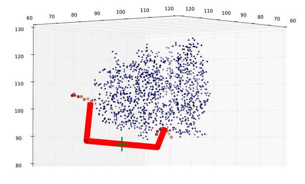
As we screen for all possible angles in a discrete manner, those angle points coordinates are regularly distributed on a sphere. As further detailed in the next sections, those spheres are defined from both ends, either once or in several steps. Then the software checks for possible straight connections of given lengths for each pair of angle points originated from both extremities.

Easy representation of the process of points generation. At first all the points from the start are generated, left. Then the points from the end are generated. Then all possible connections between the points are checked for their validity. This is done for every point from the beginning.
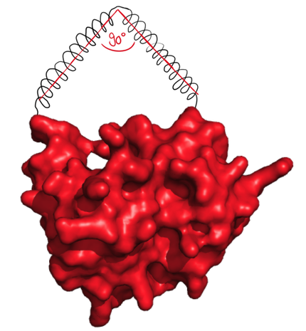
The linkers are built in a modular way, with blocks of well-defined size. From the modeling of potential linkers, we could derive 8 different alpha helical rods, all with different lengths. On top, the length of the two segments inside an angle block was always 8Å, so exchanging angle blocks do not affect the length of the linker. This means that the distance between the angle points is well defined, an essential aspect of our strategy of linker design. The software proceeds in three steps. First, it checks for the possibility of direct single alpha helix linker. for this, it applies the procedure just mentioned with spheres of radius that reasonably corresponds to the length of the short parts at the extremity of the protein. Second, it tests if a linker containing two alpha helices connected with a right angle allows the circularization. Finally it searches the possible linkers with three angle points. The next parts will explain those three steps in detail. This method has been chosen, because it could be implemented easily and efficiently in our program. However, this strategy generated paths that crossed the protein. Therefore we put big efforts in the sorting out of the paths.
Step 1
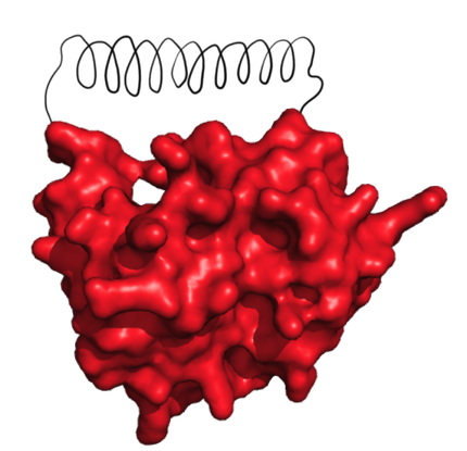
As a simple rigid linker with no angle would be easier to design and likely more thermostable than the ones containing angles, the software first checks if this simple solution is possible.
For this, we took into account the fact that proteins have some flexible amino acids at their extremities. This flexible part may come from the protein itself, but also from the 2 glycines that are included at the N-terminal part and from the extein at the C-terminal part. Those two latter parts comes from our linkers. Those parts have no preferential angles and offers a large amount of possibilities to insert fitting linkers. But this flexibility is also a drawback as we have to include this large amount of possible angles and length to our path search. In this first step, the software explicitely takes these flexible parts into account to check for the possibility of straight linkers. As the angles and the length of the flexible parts are variable, the software position their extremity on a sphere centered on the last fixed position of the structure as explained above. The radius of this sphere is incremented in a discrete manner, in 4 steps, from 5.25 Å to the maximum length of the flexible part. Then all possible straight segments between the points and the lastpoints are tested. If they are closer than 5 Å to the protein, of if they cross it, then they are rejected. If they are kept, then the software checks whether the length of the segments is compatible with the feasible alpha helices in terms of length: if the length of a given segment equal one of the 8 alpha helix lengths plus or minus 0.75 Å, then the path is eventually saved.
Step 2
The next possibilty to design more complex rigid linkers while still taking flexible ends into account with a reasonable calculation time was to reduce amount of possible angles. As we originally thought that 90° angle would be practically feasible, the software was designed to generate linkers with flexible ends and one 90° angle.
Step 3
Finally the software also provides the possibility to find paths with up to 4 edges, meaning 4 alpha helices and 3 angles. Thanks to the modularity of the possible linkers, such paths can offer the possibility to circularize theoretically any kind of protein, see figure 2).
To keep the calculation feasible in a reasonable time, we design the searching strategy so that the flexible part at the extremity are oriented in the same direction as the consecutive alpha helix. This is obviously restricting the search but as these orientations are allowed for the flexible part, this approach remains fully correct. First, potential ending points of the first alpha helical rod are calculated from the N-terminal point of the protein. The orientation is chosen in a discrete manner, with an incrementation of 5 degrees for the two angles of the spherical coordinates. The distance from the origin corresponds to the 8 possible lengths allowed by the alpha helices, as already seen in Step 2, plus a length of 0, which mimics a linker with 3 instead of 4 edges. The exact same procedure is repeated to define all the potential ending points of the second alpha helical rod starting from all the possible ending points of the first alpha helical rod. Thanks to the possibility of a length of 0 for the first and the second rods, the software also calculate paths with 2 edges. Then, the same is done only once from the C-terminal point of the protein, defining 1 edge. The final step consists in checking if the points originating from the N- and C-terminal points can be linked by an potential alpha helix, i.e. if they are separated by the appropriate distance. If any of the potential alpha helix length lies within the distance between two points plus or minus 0.75 Å, then the path is eventually saved. In the same way, if two points are directly closer than 0.75 Å, then the path is also saved.
Sorting out of paths
The previous part described the generation of paths that can connect the two extremeties of the protein irrespective of the position of these paths relative to the protein. While this allows a fast computing of the geometrical paths, this also implies that the paths that are not practically feasible need to be sorted out. This is the most time consuming part of the computing as about 1 billion paths are generated. Three criteria are considered for the sorting. The first one is the feasibility of the linker: can the software find angle patterns that correspond to the one defined by the geometrical path? This question was part of the motivation for a large modeling effort (link) to determine the possible angles between consecutive angles. This was achieved by analyzing the distribution of angles between alpha helices found in the ArchDB database. As nearly any angle could be found between 20 and 170 degrees, only few paths were actually rejected at that step. The next criteria was the position of the angle point: if they appear inside the protein, then the path is rejected. Finally, the software checks if any of the atoms of the protein is less than 5Å away from any of the alpha helices, then the path is also rejected.
Shifting paths to the patterns
The strategy described in step 3 gives a certain freedom for the rod that connect the last two angle points that were generated from the N- and C-terminal points. As this freedom is actually not permitted by the alpha helix and the angle pattern, but is permitted by the flexible part for example at the C-terminal end, the software slighty refine the path by rotating the segment that originates from the C-terminal point.
Weighting of paths
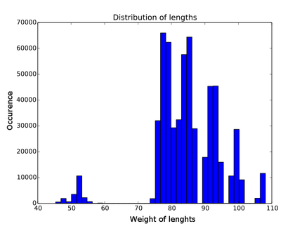
Before translating the paths into sequences and thus into linkers that can be expressed, each path needs to be evaluated for its potential capacity to enhance heat stability. For this we have identified different contributions that should be combined into one value that defines how good the linker may be and that consequently defines its ranking among all possible linkers. The smaller this value, the more we expect that the linker will enhance thermostability. An important step for all these contributions is the normalization, as explained in the next paragraphs. The first contribution we considered was the linker length. We assumed that a short linker is better to constrain the protein extremities, and that a long helix might give more flexibility. Because we wanted this value to be independent of the size of the protein, the length of the linker is normalized to the distance between the two termini. The second contribution relates to the angles used in the linker. We learned from the modeling that angles formed by a certain angle pattern follow a certain distribution. First, we assumed that the narrower the distribution, the more likely the alpha helices would actually produce this angle. Second, the angles found by the software should be as close as possible to those well-defined angles. In this case, the weight value from this contribution should be low. Then the distance of the linker to the protein is taken into account. Because the linkers should not disturb the protein in its normal environment, linkers that pass close to the protein surface are considered better linkers. The distance was defined as the minimal distance between the linker and all the atoms of the protein. As already mentioned for the sorting of the paths, a linker cannot come closer than 5 Å and this distance was used for normalization of calculated distances. After this, the places a linker should avoid are calculated. Each protein can interact with other molecules on some oarts of its surface. The user can specify where and how big those parts are. If a linker passes in front a potential molecule binding domain, the value of the corresponding path goes to infinity, so that the linker is discarded. Conversely the farther a linker is from a potential ligand binding domain, the smaller its weighting value. The user can also specify the importance of certain regions. In the end the total weighting is normalized to the amount of binding domains.
Calibrating the weighting function
Every contribution has its own distribution. You can see an example in figure
Translating paths to sequence
As already mentioned before the software is provided with two databases, one for the possible angle patterns and one for the helix patterns. The choice of the patterns was inspired by known crystal structures extracted from databases and described in different papers. A huge in silico screening for refining the preferences of the patterns was then set up using the distribution calculation system. For the complete description of search for suitable patterns, one can read the modeling page. All the possible paths are now split up at the angles and compared with the possible patterns in the databases. The most suitable patterns are identified and added together to build the paths sequence. It is important to notice that this is only possible because of the modularity of our linker patterns used as building blocks: each block, being an alpha helix or an angle pattern, is not affected by the other. Thus for each possible path, one sequence is produced.
Clustering of paths
Many different paths are represented by the same sequence ###Figure that shows, different paths have same properties, already before in the text ### and we therefore clustered such paths. The weigths for those clustered paths were then calculated by averaging the weights of the different paths that compose a cluster.
Results
DNMT1
A major motivation of our effort to design rigid linkers with angles was the circularization of the DNA methyltranferase Dnmt1. The truncation form used in our project is composed of 900 amino acids and the N- and C-terminal extremities are well separated. To circularize it, two linkers were designed: a flexible one made of glycine and serine, and a rigid one designed by the software. The rigif linkers for DNMT1 were obtained from an early state of the software. At that time the calculation took 11 days on a laptop computer with intel i5 processor and 8GB of RAM, which shows the importance of a distributed computing system for large proteins. But from that state on, the software has still improved a lot, resulting in reduced calculation time to about 1 day for DNMT1.
Feedback from wet lab
The results from the software for lysozyme were tested as described in the linker-screening part and evaluated as described in the enzyme modeling part. We have performed a large linker screening on 10 different lysozymes with different linkers. As the purpose of the lysozyme screen was the calibration of the software,those linkers (Table 1) were designed according to the four contributions previously mentioned. One of them was the shortest possible, one had the best possible angle, and so on.
| Linker | Amino acid sequence | activity | length- contribution | angle- contribution | binding site contribution | distance from surface | weightingvalue after calibration | |
|---|---|---|---|---|---|---|---|---|
| Very good linkers | ||||||||
| sgt2 | GGAEAAAKAAAHPEAAEAAAKRGTCWE | 0.7477 | 1.9205 | 6.7789 | 0.002259 | 10.525 | 114912 | |
| rigid | GGAEAAAKEAAAKAAPRGKCWE | 0.9447 | ||||||
| Average linkers | ||||||||
| may1 | GGAEAAAKEAAAKAAAAHPEAAEAAAK EAAAKAKTAAEAAAKEAAAKARGTCWE | 0.7489 | 6.2225 | 13.19 | 0.00384 | 1095.2 | 196414 | |
| ord1 | GGAEAAAKEAAAKATGDLAAEAAAKAARGTCWE | 0.956 | 4.936 | 4.639 | 0.00055708 | 220.8 | 27985 | |
| ord3 | GGAEAAAKEAAAKASLPAAAEAAAKEAAAKRGTCWE | 1.390 | 4.949 | 7.116 | 0.000545 | 261.2 | 28557 | |
| Short linkers | ||||||||
| sho1 | GGRGTCWE | 0.7087 | ||||||
| sho2 | GGAEAAAKRGTCWE | 0.5743 | ||||||
| flexible linker | GGSGGGSGRGKCWE | 0.6851 | ||||||
| linear lysozyme | no linker | 0.7039 |
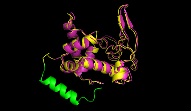
In figures 7 and 8 one can compare the modeled structure of the linker to the predicted path of the software. The lysozyme is oriented nearly in the same directions.
In the end we obtained a ranking of the in vitro tested linkers from the linker-screening and chose the parameters $\alpha, \beta, \gamma, \delta$ of the weighting function so that the ranking from the software represented the ranking from the assays. These values were at first fitted, so that the ranking predicted by the software resembles. But this could not work out perfectly because for example may1 linker was worse in every contribution than sgt2 but was tested better. Therefore the different parameters were adjusted afterwards by hand. The final values, $\alpha = 1.85 * 10 ^{-6}, \beta = 0.57 , \gamma = 50.8 * 10^6$, set up a function that could reproduce the ranking oberved in the wetlab experiments.
Discussion
The software described here allowed us to design rigid linkers with well-defined angles. This represents a major advance compared to previous approaches like [2] as these linkers can circularize any protein of known structure with any complex geometry. The feedback between the modeling and the experiment work on lysozyme activity was a crutial step in the development of the software. It allowed the testing of our approach and the calibration of the contribution of different features of the linkers to heat stability. This calibration was performed on one enzyme, and can improve in the future with the testing of more enzymes. This will also be refined thanks to a complete modeling and analysis of protein structures with linkers. Further on we could refine our assumptions on the different contributions of the weighing function. At first we assumed, that length would dominate, but the data suggests, that the contribution from omitting the substrate would be most important.
References
[1] Thornton, J.M. & Sibanda, B.L. Amino and carboxy-terminal regions in globular proteins. Journal of molecular biology 167, 443-460 (1983).
[2] Wang, C.K.L., Kaas, Q., Chiche, L. & Craik, D.J. CyBase: A database of cyclic protein sequences and structures, with applications in protein discovery and engineering. Nucleic Acids Research 36, (2008).
 "
"


