Team:IvyTech SouthBend IN/progress
From 2014.igem.org
(Difference between revisions)
| (3 intermediate revisions not shown) | |||
| Line 69: | Line 69: | ||
<li><a href="#929104">9/29/14-10/4/14</a></li> | <li><a href="#929104">9/29/14-10/4/14</a></li> | ||
<li><a href="#10511">10/5/14-10/11/14</a></li> | <li><a href="#10511">10/5/14-10/11/14</a></li> | ||
| + | <li><a href="#101218">10/12/14-10/18/14</a></li> | ||
<li><a href="#DR">Data Review 10/14/14</li> | <li><a href="#DR">Data Review 10/14/14</li> | ||
</ul> | </ul> | ||
| Line 96: | Line 97: | ||
</div> | </div> | ||
| - | <div class="ivyleft"> | + | <div class="ivymask rightmenu"> |
| + | |||
| + | <div class="ivyleft"> | ||
<div class="ivy1"> | <div class="ivy1"> | ||
| + | <!-- column 1 start --> | ||
| + | <div id="memo3g"><a name="101218">Week</a> of 10/12/14 through 10/18/14</div><br /> | ||
| + | <ul> | ||
| + | <li>Our goal was to create a microfluidic device. We used negative lithography to create a patterned wafer and the pattern in the wafer will be used as a negative master mold to create a PDMS microfluidic structure. The PDMS microfluidic structure will use the application of hydrostatic transport of a liquid media. The PDMS microfluidic structure is being adhered to a glass slide to create a sealed chamber and that will be used to transport liquids through microfluidic channels. A microfluidic channel is commonly defined as having one or more dimension less than 100 microns in size. Transport mechanisms used by microfluidics to transfer liquids include capillary forces, hydrostatic pressure gradients, electrokinetics, pumps, magnetism and digital arrays. Microfluidic channel material is important to consider when choosing the transport mechanism.</li><br /> | ||
| + | <li>The goal of the experiment is to create a master mold with a patterned wafer, to use that master mold to create a PDMS microfluidic device and to transport liquids through the PDMS microfluidic device. </li><br /> | ||
| + | <li>The wafers are now primed for photoresist application. The photoresist being used is SU8-25 which should give a thickness of approximately 25 microns. We decided to try to increase the thickness of the resist to 75-80 microns by slowing the spin rate to 1000 rpm and applying the resist extra thick. Room lights are turned off and special orange lights that filter out light below 530 nanometers are used because SU8-25 photoresist is sensitive to ultraviolet light. The SU8-25 photoresist is applied using a static spin. One at a time each wafer is placed on a two inch chuck and a centering spin is done to ensure the wafer is centered. An eight milliliter pipette is used to apply the SU8-25 photoresist to the wafer. The pipette is used to cover the entire wafer with SU8-25 photoresist and to remove any air bubbles. The first step of the recipe is a 5 second dwell at 500 RPM with a ramp rate of 100 RPM per second. The second step of the recipe is a 40 second dwell at 1000 RPM, we changed the exposure time from 45 to 60 seconds. A soft bake on a hot plate is performed on the wafer (after the photoresist was spun on) to remove any solvents and harden the photoresist. The wafer’s soft bake is started at 65° C and after three minutes the hot plate temperature is raised to 95° C for an additional seven minutes of baking. </li><br /> | ||
| + | <li>We then performed a post exposure bake for 1min at 65 ° C then raised the hot plate to 95 ° C for additional 3 minutes. After PEB the wafer is developed by placing it in a bath of developer and gently swirled for five minutes to develop the pattern in each wafer. The wafers are removed from the bath, rinsed with isopropanol and air dried. The wafers are then brought back down to the nanotech lab and images are taken of them with the optical microscope. We the measured the thickness on the profilometer and found we hit our mark at 80,162 Å .</li><br /> | ||
| + | <li>The procedure we used came from a microfluidics nanotechnology negative lithography lab. In preparing the wafers they are cleaned with acetone, isopropanol, deionized water and dried with an air can. The wafers go through a dehydration bake on a hot plate at 110° C for three to four minutes to remove any residual liquids. A HMDS application is performed on the wafers to improve photoresist adhesion to the wafer substrate. HMDS is applied to the wafers by putting them into a sealed but non-vacuumed chamber with an open bottle of HDMS for 15 minutes. After removal from the chamber the wafers go through another dehydration bake on a hot plate for 15 seconds at 110° C. </li></br> | ||
| + | </ul> | ||
| + | <!-- column 1 end --> | ||
| + | </div> | ||
| + | <div class="ivy2"> | ||
| + | <!-- column 2 start --> | ||
| + | <p><center><img src="http://i.imgur.com/vIsgpcX.png" style="width: 100%;max-height: 100%" /></center></p> | ||
| + | <!-- column 2 end --> | ||
| + | </div> | ||
| + | </div> | ||
| + | </div> | ||
| + | |||
| + | <div class="ivymask leftmenu"> | ||
| + | |||
| + | <div class="ivyleft"> | ||
| + | <div class="ivy1"> | ||
| + | <!-- column 1 start --><br /> | ||
| + | <div id="memo2g"><a name="92128">Week</a> of 10/5/14 through 10/11/14</div> | ||
| + | <ul> | ||
| + | <li>This week we began work on the nanotechnology aspects of our project. The main focus was working on the microfluidic channel, the volume of space that is going to hold the water sample while the biochemical reaction for beta-galactosidase is taking place. We used negative lithography to cast a master mold of a chamber we designed and thought would be best suited for our device. After the mold was cast and sent through numerous bake sessions, it was inspected and determined to be an acceptable mold. We then made a polydimethylsiloxane (PDMS) mixture with a 10:1 ratio with a curing agent. After pouring it into the mold, great care was taken to ensure there were no bubbles left in the PDMS mixture. After being left to dry and hardened, a plasma generator was used to bind the cut out piece to a glass slide. The patterned wafer negative mold microfluidic chamber width is 14.562mm. Its height is 21.3μm at the sidewall and 22.3μm in the middle. A single pillar width is 1.611mm and “height” is 20.8μm. The three microfluidic channel widths are 0.6688mm, 0.5472mm and 0.6080mm while the middle microfluidic channel height is 20.9μm. It can hold a water sample of 6.75 uL. Unfortunately, after testing it with ink we got negative results. Two chambers were tested and both collapsed. We are going to try again using shorter channels and combining pillars so there is a better support system. </li><br /> | ||
| + | </ul> | ||
| + | <!-- column 1 end --> | ||
| + | </div> | ||
| + | <div class="ivy2"> | ||
| + | <!-- column 2 start --> | ||
| + | <p><center><img src="http://i.imgur.com/v78FAXF.png" style="width: 75%;max-height: 75%" /></center></p> | ||
| + | <!-- column 2 end --> | ||
| + | </div> | ||
| + | </div> | ||
| + | </div> | ||
| - | <div class="ivymask | + | <div class="ivymask rightmenu"> |
<div class="ivyleft"> | <div class="ivyleft"> | ||
<div class="ivy1"> | <div class="ivy1"> | ||
Latest revision as of 23:12, 17 October 2014
Data Review 10/14/14

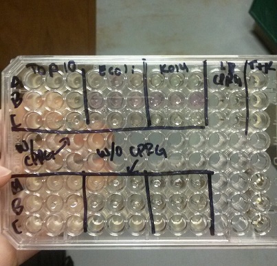
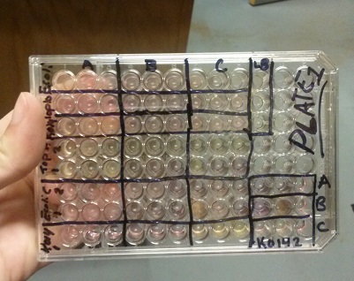
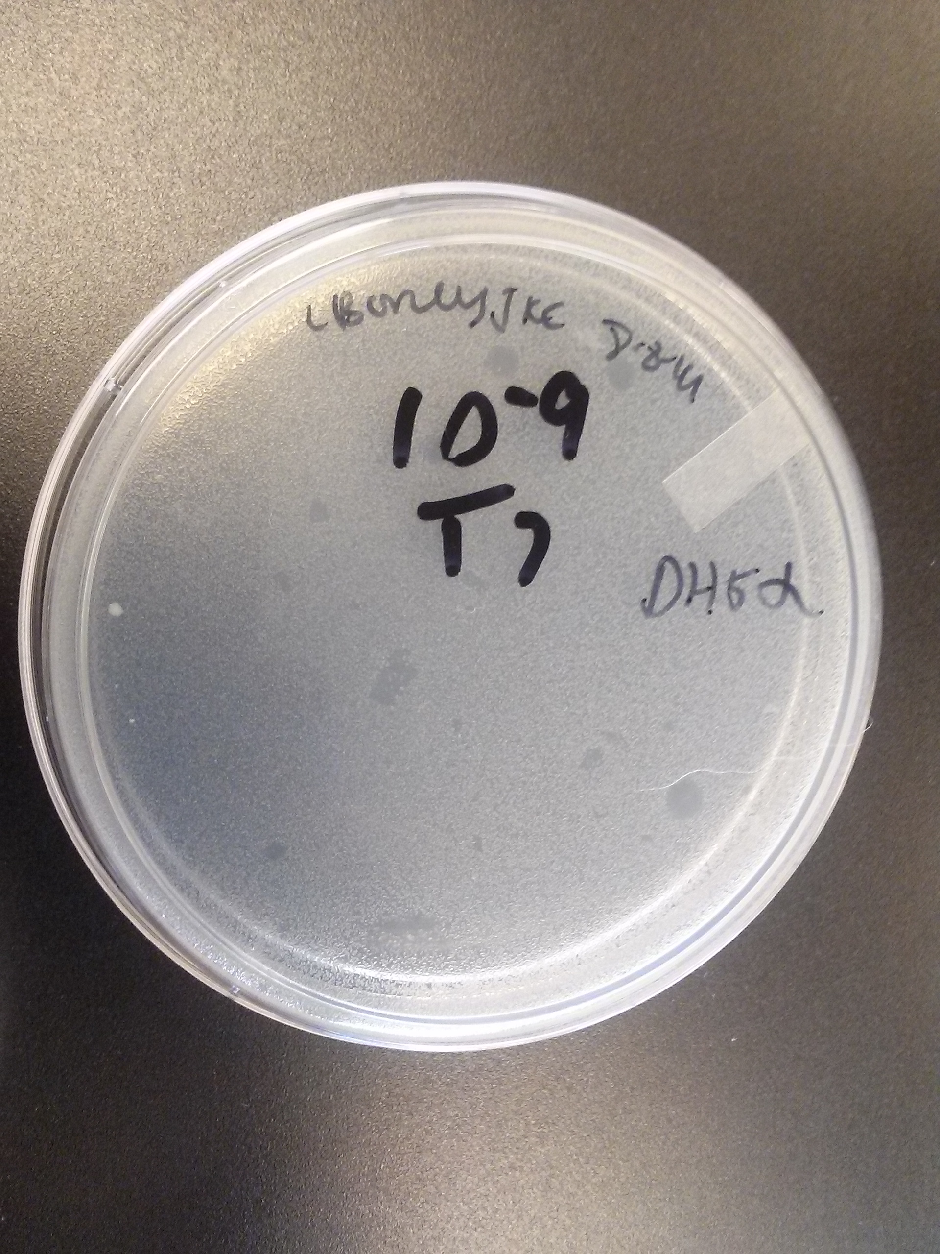
- Data from a replication of Stanick’s assay with K1477014: Cells were grown overnight in LB or LB/glucose. Cells in LB were stimulated with 200 uM IPTG for 1 hour and then all cell cultures were divided into 1mL aliquots to which calcium chloride and magnesium sulfate were added. T7 bacteriophage (1 x 10^5 pfu) was added to the appropriate culture and the absorbance at A600 was followed until virus lysis was evident. Cell cultures were then transferred to SpinX filter devices and the media was separated from the cells. Aliquots of filtrates from cells only, T7-treated cultures, or from T7-treated culture were transferred to a microtiter plate. Buffer Z with 2 mercaptoethanol was added and absorbance at 415 nm was determined after 30 minutes.
- Results: Both E.coli C and K1477014 cells stimulated with IPTG “leaked” β-gal activity (Cells only). Top10 cells were negative as expected. β-gal activity was suppressed in all cell lines by glucose as expected. T7 treatment resulted in an increased release of β-gal activity from both E. coli C and K1477014. The combination of T7 lysates from Top10 cells stimulated with IPTG and K1477014 cells grown in glucose did not show any β-gal activity. .
- Conclusion: Cells stimulated with IPTG and subjected to this protocol release β-gal activity. This might be due to β-gal activity that accumulated in the media as the cells grew. Another possibility is that β-gal activity was released when the calcium chloride or magnesium sulfate solutions were added before virus lysis or perhaps released during centrifugation of the cells in the SpinX columns.
- Most important however is that β-gal activity was found in the medium of lysed and unlysed K1477014 suggesting that the LacZ alpha and omega polypeptides stay combined once they are released! That is great news!
- T7 treatment caused an increase in the release of β-gal enzyme from the E. coli C and the β-gal enzyme (alpha-omega polypeptide combo) from K1477014.
- Unfortunately, the combination of T7 lysates of Top 10 cells treated with IPTG, which should have formed LacZ omega polypeptides and the K1477014 cells treated with glucose, which should have formed only LacZ alpha polypeptides, did not have any detectable β-gal activity.
- This lack of activity could be due to the slow association of the alpha and omega fragments, maybe slowed by the Buffer Z and calcium and magnesium salts or, worse, it means that the alpha and omega polypeptides have to associate inside a cell to be joined into a working enzyme. We can study this further by letting the combination of fragments incubate together for hours in hopes that β-gal activity appears. If it does that is great because that is the proof of principle that we are after.
Week of 8/3/14 through 8/9/14
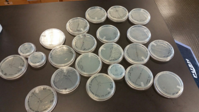
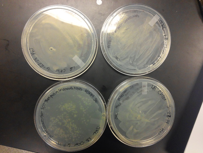
- During this week, the team realized that the contamination was coming from our stock of cells that was being kept in the -80C freezer. We have no idea how they became contaminated, seeing as continued to use the line of cells we froze for a week after we froze them, but before any contamination occurred. Nonetheless, one of our advisers has procured a new stock of top 10 E. coli cells for us to use.
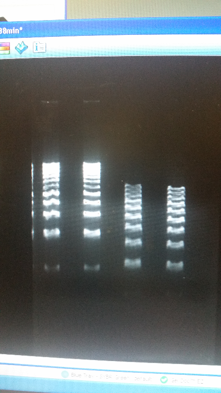
- After unsuccessful runs of electrophoresis gels, we have run out of DNA to try to measure. So, we took some time out this week to streak, grow, and purify lines of our K1477014 and K1477030 parts on both pSB1C3 and pSB1AT3 backbones.
Week of 7/13/14 through 7/19/14
- This week we worked towards switching our part's backbone from pSB1AT3 to pSB1C3. We had some difficulty doing this. The first attempt was fruitless, but on our second attempt we had success and we now have a stock of our part on a chlor-resistant backbone.
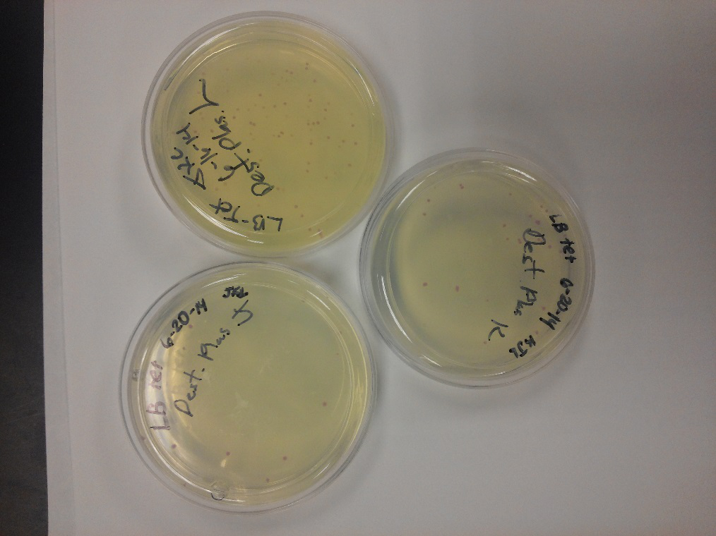
- Unfortunately, We no longer have any stock of our original part. So, now we are again following the 3A Biolabs Biobrick Assembly Manual to reconstruct our parts K1477014 and K1477030. Our first try yielded nothing.
- Our second run through of the protocol resulted in the growth of red colonies on chlor plates after electroporation of our part into Top 10 cells. However, we need white colonies to grow because this will point towards the rfp being repressed when the three parts come together. Red colonies are a sign that we did not have a successful assembly of our parts.
Week of 5/25/14 through 5/31/14
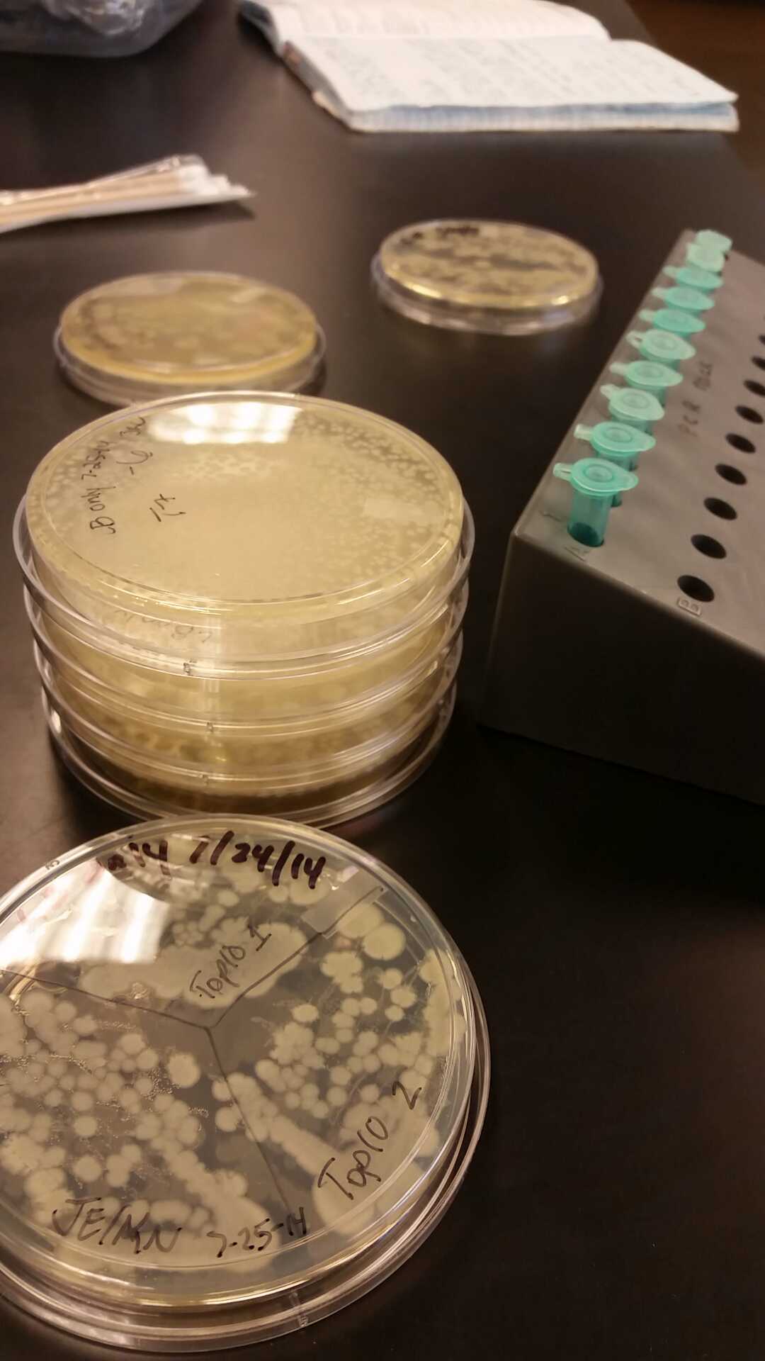
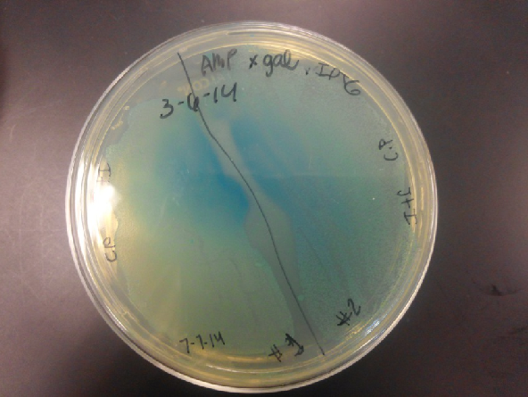
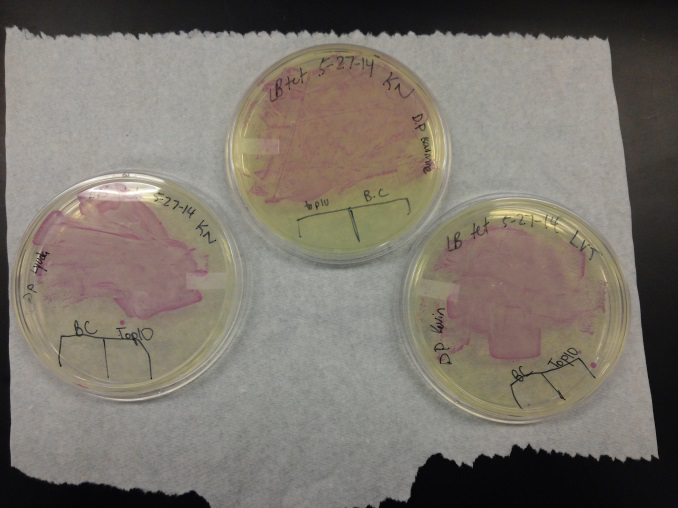
- We transformed Top 10 cells through electroporation with registry parts K112806 (Endolysin,) I732020 (LacZoperon Mutant,) J23102 (p-con) and I712074 (T7 promoter.)
- After streaking on plates, and leaving them in the incubator for a day, there was growth on all plates, showing that a successful transformation occured.
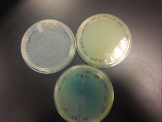
- Plates containing J23102 were red-another sign of success. Unfortunately, it looks like contamination has arisen as well, and is spreading on plates with I712074 and K112806 growth.
- The contamination persisted all week, but we were able to get plates with transformed parts that contained no contamination growth.
- We then ran a DNA purification protocol of J23102 and I732020 to get them ready for a biobrick assembly protocol.
 "
"


