Team:Aachen/Project/Measurement Device
From 2014.igem.org
(→Hardware) |
|||
| Line 76: | Line 76: | ||
<span class="anchor" id="watsonhardware"></span> | <span class="anchor" id="watsonhardware"></span> | ||
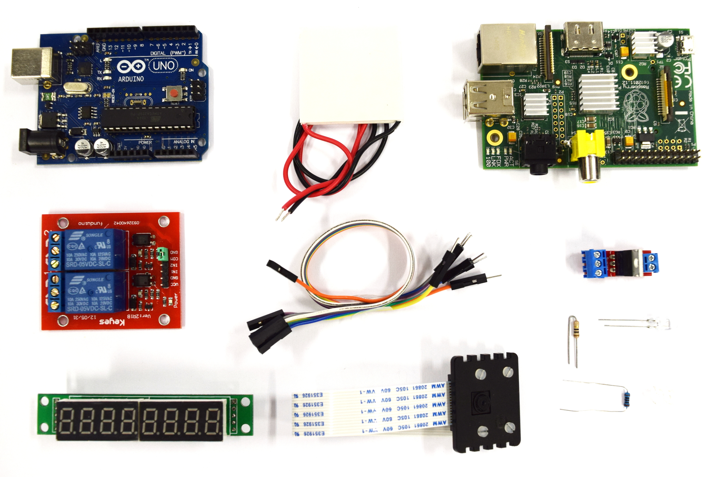
| - | {{Team:Aachen/Figure|Aachen_Device_Elektronikkomponenten1.jpg|title=Hardware components||width=520px}} | + | {{Team:Aachen/Figure|Aachen_Device_Elektronikkomponenten1.jpg|title=Hardware components|subtitle=From right to left, top: ; middle: ; bottom: .|width=520px}} |
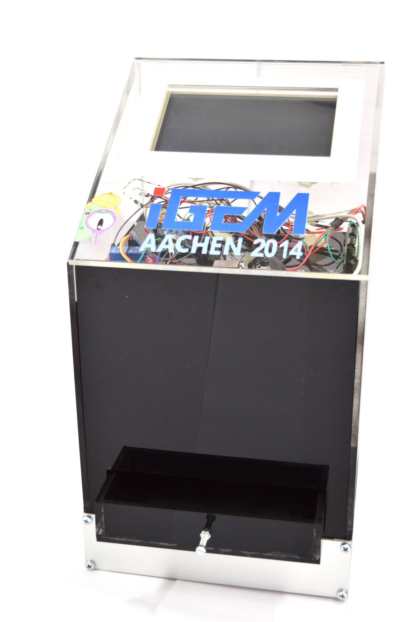
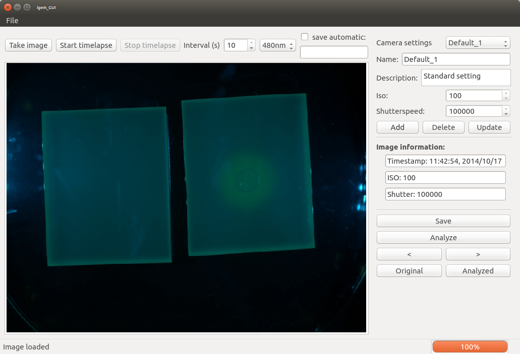
Our hardware consists of the casing and the electronical components. The casing which can be seen in the first section was build from laser cutted acrylic glass. <html><br/></html> | Our hardware consists of the casing and the electronical components. The casing which can be seen in the first section was build from laser cutted acrylic glass. <html><br/></html> | ||
The electronic circuit is a combination of the components displayed in the image above. We combined the Raspberry Pi - a small single-board computer running a Linux operating system - and an Arduino board which is a programmable microcontroller. The Arduino operates the excitation LEDs and a Peltier heater for incubation. For taking images of the sensor chips we used the Raspberry Pi camera module which is directly connected to the board.<html><br/></html> | The electronic circuit is a combination of the components displayed in the image above. We combined the Raspberry Pi - a small single-board computer running a Linux operating system - and an Arduino board which is a programmable microcontroller. The Arduino operates the excitation LEDs and a Peltier heater for incubation. For taking images of the sensor chips we used the Raspberry Pi camera module which is directly connected to the board.<html><br/></html> | ||
Revision as of 13:26, 17 October 2014
|
|
|
|
|
|
 "
"
