 "
"
Team:Heidelberg/pages/LOV
From 2014.igem.org
Contents |
Introduction
Protein splicing allows for the introduction of major changes to a proteins sequence and structure even after translation. Although this mechanism alone offers a huge amount of possible applications highlighted in our toolbox, it would be advantageous to have control over the time and location of the splicing reaction especially for in vivo applications. However, the fact that inteins are attached to the protein they splice off from makes induction in whatever way rather difficult.
Controlling Inteins
Different ways exist for controlling the intein splicing reaction. In the literature this is mostly referred to as conditional trans splicing (CTS) or conditional protein splicing (CPS). The oldest method of inducing protein splicing is to chemically control the activity of inteins by changing the pH or redox state of their environment. This has been achieved for a multitude of inteins such as Ssp DnaB [1] or Mtu recA [2]. Yet the major drawback is obvious: These methods are only effectively applicable in vitro and usually depend on complexly purified reagents.
Within the past decades, more advanced systems were designed involving the binding of different ligands or the fusion of inteins to various protein domains. For example Mootz et al. succeeded in inhibiting the splicing reaction of an synthetically engineered version of Ssp DnaE through the addition of rapamycin [3]. Similarly, the S. cerevisiae VMA intein has been conditionally activated by rapamycin induced complementation of FKBP and FRB protein domains. There have previously been attempts to light induce inteins with an analogous system in which the VMA intein halves are fused to the chromoproteins Phytochrome B (PhyB) and Phytochrome Associated Factor 3 (PIF3) [4]. Upon light induction at 660 λ nm PhyB and PIF3 assemble bringing the intein halves together to initiate splicing. Although most certainly a useful tool, these principle can only work for inteins with low affinity to each other and therefore with rather low reaction rates. When using faster inteins, the corresponding halves bind to each other with significantly higher affinity and thereby start the splicing reaction independently from the binding state of their coupled protein domains.
We therefore came up with a new method to inhibit an intein's function light-dependently using LOV2 domain photocaging.
The As LOV2 domain
As LOV2 is the second Light-Oxygen-Voltage domain from the Avena sativa phototropin 1. In its host organism, the common oat, phototropin 1 is a blue-light receptor involved in the response of growth to environmental light conditions and may be responsible for the opening of stomata and the movement of chloroplasts [5]. LOV2 mainly consists of a flavin mononucleotide (FNM) -binding core containing a FNM as chromophore, as well as a helical structure on the C-terminus, the J-alpha helix. Upon excitation with light, a cysteine within the core covalently binds the activated FMN, which induces a conformational change resulting in the protrusion of the formerly concealed J-alpha helix [6].
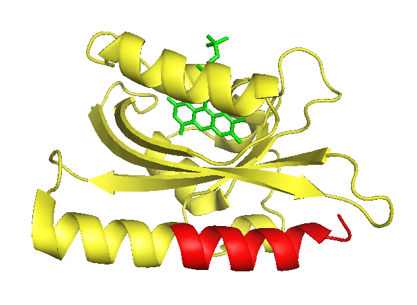
The J-alpha helix is clearly identifiable in the front bottom. The part suitable for photocaging (that is the part downstream of the I539 is colorised in red. The flavin mononucleotide chromophore is shown in green.
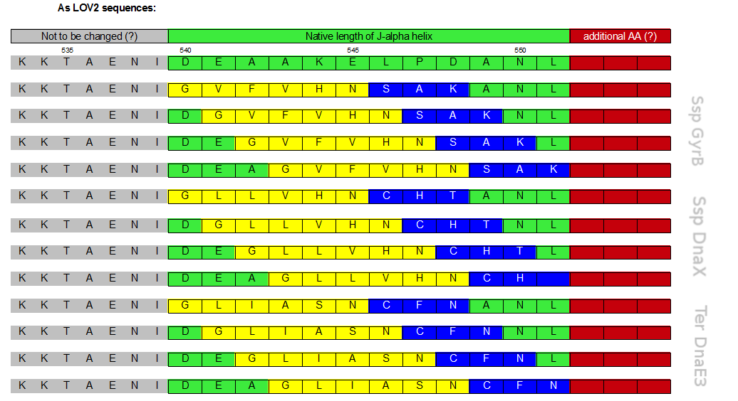
As in LOV photocaging inhibition is not achieved by merely blocking an active centre but by completely hiding the whole binding partner we assessed the latter strategy as the most promising. Because of the C-terminal location of the J-alpha helix, the place that photocaging takes place in, an intein that is hidden within the LOV domain and splices off a fused protein without creating a significant scar needs to be a C-intein. It has been suggested that the length of the caged peptide itself determines the success of the photo caging [10]. Thus, we extensively screened the literature and discovered a set of only six amino acids long C–inteins.
S11 split inteins
Interestingly, there seem to exist only very few inteins with small C-terminal halves. The shortest and therefore most suitable were the S11 split inteins, engineered and thoroughly, but solely described by Lin et al. [11] . S11 inteins are engineered from mini-inteins, meaning that, unlike most other inteins, they do not have an internal homing endonuclease domain. Naturally, they are not trans-, but cis-splicing inteins and their crystal structure reveals twelve β-strands. To gain very small C-terminal split inteins, they were artificially separated between the 11th and 12th β-strand resulting in a 120-160 aa N- and 6 aa C-intein. We decided to use the Ssp DnaX, Ssp GyrB and Ter DnaE3 inteins since there properties were promising i.e. they showed the highest splicing activity.
Cloning and Methods
Rational Design of inLOV constructs
The J-alpha helix is clearly identifiable in the front bottom. The part suitable for photocaging (that is the part downstream of the I539 is colorised in red. The flavin mononucleotide chromophore is shown in green.
Initially a screening for the caging of three different S11- inteins, namely SspDnaX, SspGyrB and TerDnaE-3, at various positions within the J-alpha helix of the LOV domain was planned (Figure 3). The best split fluorescent protein was thought to provide an easy read-out for the best combination of caging position and C-terminal split intein. Unfortunately, we encountered many problems: the assembly construct with two insertion sides in which the LOV domain ought to be embedded for an easy exchange of caging positions via golden gate cloning was not ready at this time point. Secondly, a screening for the best split fluorescent protein turned out to be more time intensiv than expected.
The J-alpha helix is clearly identifiable in the front bottom. The part suitable for photocaging (that is the part downstream of the I539 is colorised in red. The flavin mononucleotide chromophore is shown in green.
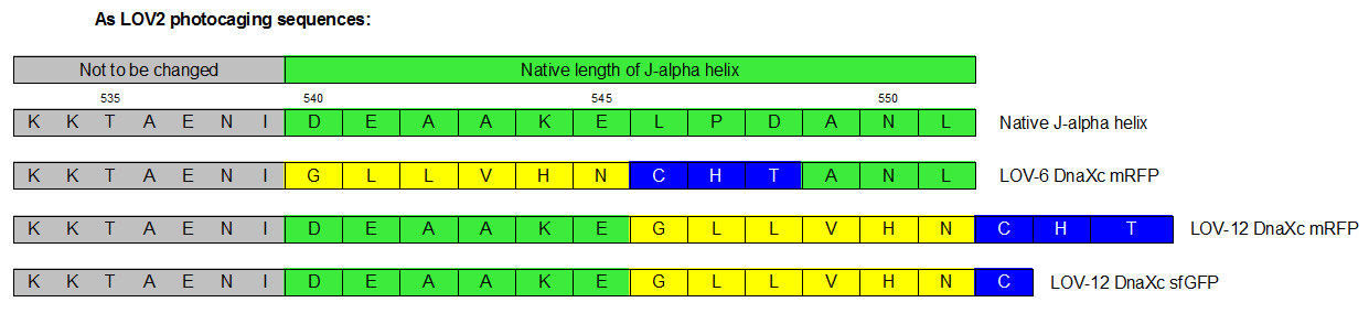
Therefore we designed a fast track cloning strategy with solely two caging positions of one intein in the alpha-helix and two split fluorescent proteins. In case of the S11- inteins, we chose SspDnaX, since they were described as the most efficient C-terminal S11 intein [11]. Previous studies showed that the amino acid sequence of the J-alpha helix in front of the isoleucine at position 539 (I539) should not be changed, in order to preserve its reactivity to light [10]. However the sequence following I539 can be adapted to a small peptide sequence. We caged SspDnaX at the two most extreme positions, believing that those would result in the greatest differences in caging efficiency. The LOV - 12 mutant represents the caging of SspDnaX right after I539, resulting in the deletion of all remaining amino acids (-12) of the J-alpha helix. In the mutant LOV - 6, the short C - intein occupies the SspDnaX at the very end of the helix, resulting in the deletion of only 6 original amino acids (figure 4). In our sfGFP reconstitution assay, we already established an approach to easily read-out the intein splicing reaction. However in this assay we used the NpuDnaE inteins, which were known to splice even with unnatural exteins as far as the cysteine of the C-terminal extein is present. Therefore we obtained only this one amino acid scar in the spliced product, which can be crucial for the restoration of fluorescence in front of the chromophore region (65-67). It is not known if same assumptions can be made for SspDnax. To test this, we chose one LOV mutant using the sfGFP as split fluorescent protein with only one extein flanking the intein (figure 4, mutant 3). To provide a backup if SspDnaX does not splice with only one extein, we also designed two LOV mutants with split mRFP. In the case of mRFP, we decided for split position 168/169, since this position was already successfully demonstrated in bimolecular fluorescence complementation [12]. The split position is located between β – barrel 8 and 9, which provides enough space for larger insertions.
Cloning strategy
The three LOV mutants, namely LOV-12 SspDnaX-sfGFP, LOV-12SspDnaX-mRFP and LOV-6SspDnaX-mRFP, were created via a fast track cloning strategy using CPEC. Employing the same method, constructs were generated that do not contain the LOV domain. Both, controls that should be able to conduct the splicing reaction and controls that contain mutated intein residues at the splicing side preventing the splicing reaction were produced. Subsequently the C - terminal SspDnaX containing the LOV domain and the N-terminal construct were cloned in bisctronic expression backbone using standard biobrick cloning.
Measurement of reconstituted fluorescent protein
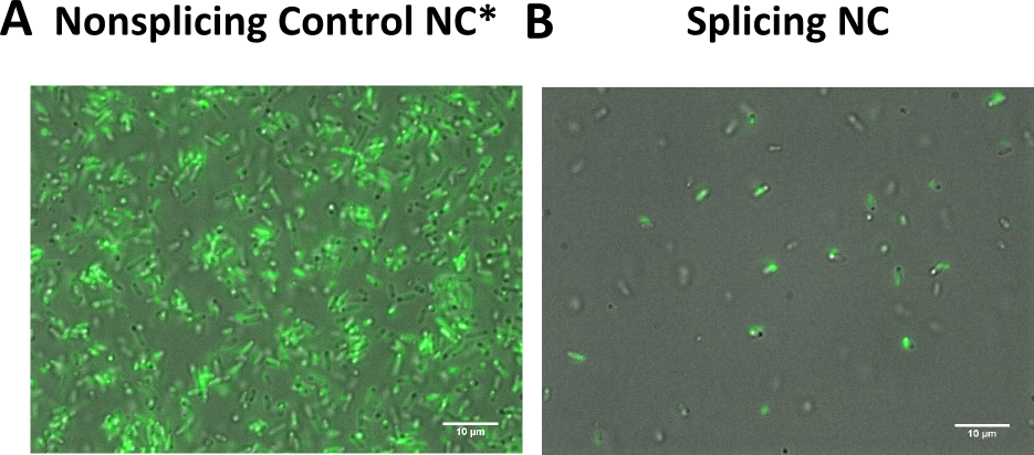
We transformed all constructs in BL21(DE3) to allow expression under the T7 promoter. 5ml cultures were inoculated with 500 µl of an overnight culture and induced with 1mM as soon as the cultures reached the OD600 of 0.8. The cultures incubated at 37 °C for further 1-2 hours. Subsequently the cultures were left on room temperature as it is described in the paper that originally describes the S11 inteins []. Simultaneously all cultures were portioned and distributed on a 24 well plate and either illuminated with blue light of 470 nm for 30 min to 12 hours or kept in the dark for the same period of time. All samples were irradiated to either allow the conformational change of the LOV domain or prove the invulnerability against phototoxicity. The fluorescence was measured with the FACS using an excitation wavelength of 488 nm and emission spectra of 497 to 522 nm for sfGFP and excitation wavelength 561 nm with an emission spectra of 602 to 662 nm for mRFP. The samples were diluted 1:1000 and every FACS run analyzed 100000 events. To validate our results we conducted several assays with a series of biological replicates following the same experimental layout. In order to analzye a Western Blot the cells were harvested by centrifugation for 5 min at 8000 rpm at 4 °C. The supernatant was discarded and the pellet frozen in liquid nitrogen and stored at 4 °C. After collecting all samples of each time point, the pellet was re-suspended in 50 µl Lämmli-Buffer and heated at 95°C for 10 minutes. The samples were once again centrifuged and 2 µl of the supernatant was diluted with 10 µl Lämmli-Buffer. 6µl of each dilution was loaded on the SDS-PAGE, either stained via Coomassie solution or visualized in the Western Blot using His-antibodies.

The J-alpha helix is clearly identifiable in the front bottom. The part suitable for photocaging (that is the part downstream of the I539 is colorised in red. The flavin mononucleotide chromophore is shown in green.

Agarose gel that shows colony PCRs of the NpuDnaEc- sfGFPc half and sfGFPn-NpuDnaEN half, which was assembled with our expression vector pSBX1K3 via CPEC. Colony PCR of NpuDnaEc- sfGFPc results in a band of 1074 bp and sfGFPN-NpuDnaEN in a band of 940 bp.

Agarose gel that shows colony PCRs of the NpuDnaEc- sfGFPc half and sfGFPn-NpuDnaEN half, which was assembled with our expression vector pSBX1K3 via CPEC. Colony PCR of NpuDnaEc- sfGFPc results in a band of 1074 bp and sfGFPN-NpuDnaEN in a band of 940 bp.

Agarose gel that shows colony PCRs of the NpuDnaEc- sfGFPc half and sfGFPn-NpuDnaEN half, which was assembled with our expression vector pSBX1K3 via CPEC. Colony PCR of NpuDnaEc- sfGFPc results in a band of 1074 bp and sfGFPN-NpuDnaEN in a band of 940 bp.

The J-alpha helix is clearly identifiable in the front bottom. The part suitable for photocaging (that is the part downstream of the I539 is colorised in red. The flavin mononucleotide chromophore is shown in green.
The J-alpha helix is clearly identifiable in the front bottom. The part suitable for photocaging (that is the part downstream of the I539 is colorised in red. The flavin mononucleotide chromophore is shown in green.
Results
During the planning phase two preparatory experiments were run to test the conditions for light induction: Please visit conditions testing to read more about the procedures and results.
Screening
List of constructs used
The cloning was performed on the basis of our two-gate assembly part. However, due to the need for fast cloning, all constructs were made CPEC.
| split N-protein and N-intein |
| split C-intein and C-protein |
| split non-splicing N-protein and N-intein |
| split non-splicing C-intein and C-protein |
| LOV domain with caged C-Intein position 6 |
| LOV domain with caged C-intein position 12 |
| (only for mRFP: LOV domain with BsaI cloning site for further customized caging positions) |
| mutated positive controls |
For split sfGFP all N-terminal splicing-partner and control constructs were taken from the split fluorescent protein assay.
Discussion
Outlook
reference to Cas9 + possible applications (Philipps idea)
References
[1] Lu, W. et al. Split intein facilitated tag affinity purification for recombinant proteins with controllable tag removal by inducible auto-cleavage. J. Chromatogr. A 1218, 2553–60 (2011).
[2] Wood, D. W., Wu, W., Belfort, G., Derbyshire, V. & Belfort, M. A genetic system yields self-cleaving inteins for bioseparations. 889–892 (2002).
[3] Brenzel, S. & Mootz, H. D. Design of an intein that can be inhibited with a small molecule ligand. J. Am. Chem. Soc. 127, 4176–7 (2005).
[4] iGEM team Queen's University, Kingston, ON, Canada 2014 https://2014.igem.org/Team:Queens_Canada/Project
[5] Deblasio, S. L., Luesse, D. L. & Hangarter, R. P. A Plant-Specific Protein Essential for Blue-Light-Induced Chloroplast Movements 1. 139, 101–114 (2005).
[6] Herrou, Julien, and Sean Crosson. Function, structure and mechanism of bacterial photosensory LOV proteins. Nature reviews microbiology 9.10 (2011). 713-723.
[7] Wu, Yi I., et al. A genetically encoded photoactivatable Rac controls the motility of living cells. Nature 461.7260 (2009), 104-108.
[8] Renicke, Christian, et al. A LOV2 domain-based optogenetic tool to control protein degradation and cellular function. Chemistry & biology 20.4 (2013), 619-626.
[9] Niopek, Dominik, et al. Engineering light-inducible nuclear localization signals for precise spatiotemporal control of protein dynamics in living cells. Nature communications 5 (2014).
[10] Yi, Jason J., et al. Manipulation of Endogenous Kinase Activity in Living Cells using Photoswitchable Inhibitory Peptides. ACS Synthetic Biology (2014).
[11] Lin, Y. et al. Protein trans-splicing of multiple atypical split inteins engineered from natural inteins. PLoS One 8, e59516 (2013).
[12] Jach, G., Pesch, M., Richter, K., Frings, S., & Uhrig, J., F. An improved mRFP1 adds red to bimolecular fluorescence complementation. Nature Methods, 3, 597-600 (2006).
[1] Aranko, A. S., Oeemig, J. S., Kajander, T. & Iwaï, H. Intermolecular domain swapping induces intein-mediated protein alternative splicing. Nat. Chem. Biol. 9, 616–22 (2013).
[2] Strickland, D. et al. TULIPs: tunable, light-controlled interacting protein tags for cell biology. Nat. Methods 9, 379–84 (2012).
[12] Schwartz, E. C., Saez, L., Young, M. W. & Muir, T. W. Post-translational enzyme activation in an animal via optimized conditional protein splicing. Nat. Chem. Biol. 3, 50–4 (2007).