Team:ETH Zurich/project/background/modelingsimple
From 2014.igem.org
Pattern Formation
Logic Gate
We want to form a pattern (a motif) on a grid of bacterial colonies. Our output signal is binary: a bacterial colony is either in an on-state or in an off-state. The on-state can be read out by the green fluorescence.
Each bacterial colony has two parents. Those parents emit a signal, if they are on. The bacterial colony can differentiate the two signals it gets from its parent. Depending on the signals received by a bacterial colony, it will switch on or off. This is the principle of a logic gate.
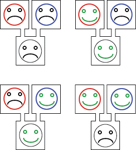
In our project, we are using a particular logic gate, named XOR. Here is an example: imagine your bacterial colonies are either happy or unhappy. If they are happy, they send a signal to their children, inviting them to a party. If a colony is invited to one party (by either of its parents), it becomes happy. If it is not invited to any party, it is unhappy. If a colony is invited by both its parents, it becomes unhappy (because there is here a dilemma).
Cellular Automata
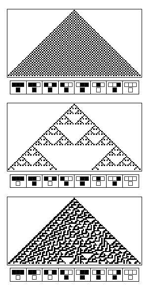
A cellular automaton corresponds to a repetitive use of the same logic gate. This logic gate is called the rule of the cellular automaton.
First, a cellular automaton needs a grid of off-state entities. Each row is the child from another row and a parent to the next row. If one well is put on in the first row, the rule is computed in the second row from this parent configuration. Then, the third row computes its state given the state of the second row and so on. These consecutive updates leads to the emergence of complex pattern. These cellular automata were studied by Wolfram [11]
 "
"

