Team:Aachen/OD/F device
From 2014.igem.org
(→OD device) |
(→Building your own OD/F device) |
||
| Line 83: | Line 83: | ||
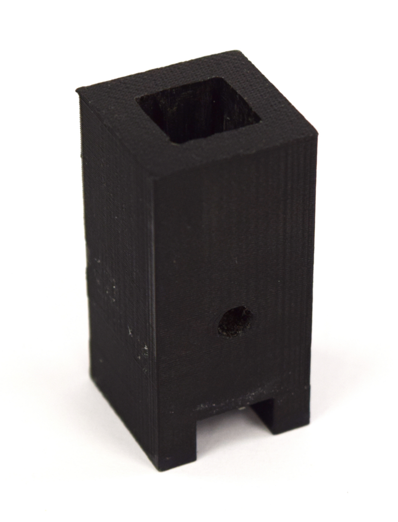
| [[File:Aachen_ODF_11.JPG|150px]][[File:Aachen_ODF_10.JPG|150px]] || Next we want to assemble the cuvette holders. On the side with the square hole attach the light-to-frequency sensor with glue. For the OD case place the orange LED opposite, or for fluorescence, the LED in the hole in the bottom. Make sure to close any remaining open hole! | | [[File:Aachen_ODF_11.JPG|150px]][[File:Aachen_ODF_10.JPG|150px]] || Next we want to assemble the cuvette holders. On the side with the square hole attach the light-to-frequency sensor with glue. For the OD case place the orange LED opposite, or for fluorescence, the LED in the hole in the bottom. Make sure to close any remaining open hole! | ||
|- | |- | ||
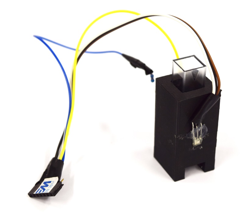
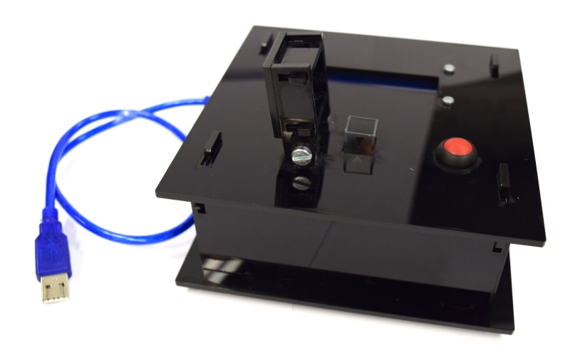
| - | | [[File:Aachen_ODF_12.JPG|300px]] || Your final assembly should then look like this. | + | | [[File:Aachen_ODF_12.JPG|300px]] || Your final assembly should then look like this. Now place the correct filter into the cuvette holder, directly in front of the sensor. Make sure that the filter does not degrade due to the glue! |
|- | |- | ||
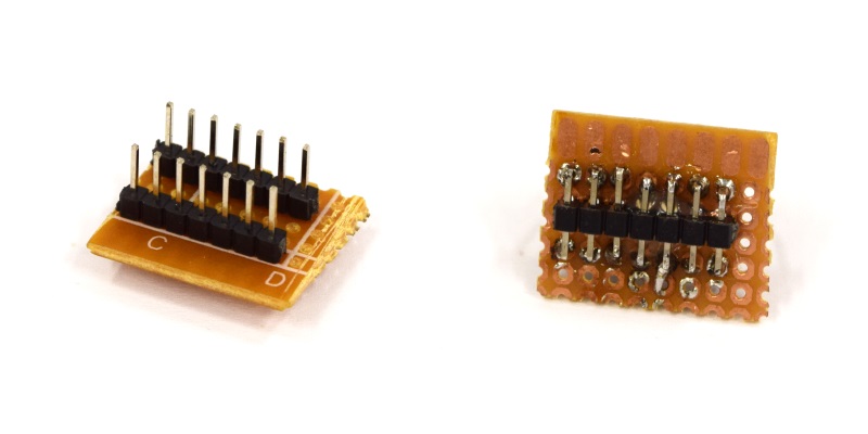
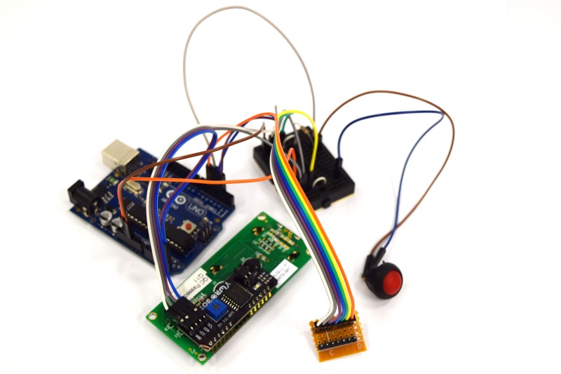
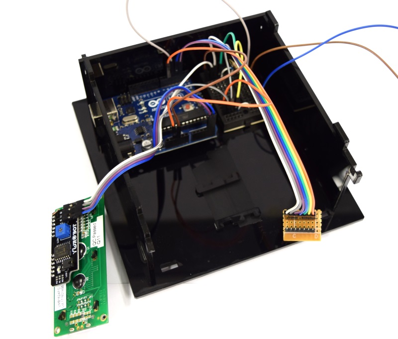
| [[File:Aachen_ODF_14.JPG|300px]] || As the case can be used for both, fluorescence and OD measurement, we use a combined plug. Just three header rows (7 pins) and connect them as we did. | | [[File:Aachen_ODF_14.JPG|300px]] || As the case can be used for both, fluorescence and OD measurement, we use a combined plug. Just three header rows (7 pins) and connect them as we did. | ||
Revision as of 23:11, 9 October 2014
|
|
|
|
 "
"
