Team:Brasil-SP/Project/Device
From 2014.igem.org
Laiscbrazaca (Talk | contribs) |
IvanRSilva (Talk | contribs) |
||
| Line 94: | Line 94: | ||
# NGE PN, ROGERS CI and WOOLEY AT. Advances in microfluidic materials, functions, integration, and applications. <b>Chemical reviews</b>, 2013, 113.4:2550-2583. | # NGE PN, ROGERS CI and WOOLEY AT. Advances in microfluidic materials, functions, integration, and applications. <b>Chemical reviews</b>, 2013, 113.4:2550-2583. | ||
# MALECHA K, GANCARZ I and GOLONKA LJ. A PDMS/LTCC bonding technique for microfluidic application. <b>Journal of Micromechanics and Microengineering</b>, 2009, 19.10:105016. | # MALECHA K, GANCARZ I and GOLONKA LJ. A PDMS/LTCC bonding technique for microfluidic application. <b>Journal of Micromechanics and Microengineering</b>, 2009, 19.10:105016. | ||
| - | # WIDMER AF, FREI R. Decontamination, disinfection and sterilization. In: Murray PR, Ed. Manual of Clinical Microbiology. 7th edn. Washington, DC: American Society for Microbiology 1999 | + | # WIDMER AF, FREI R. Decontamination, disinfection and sterilization. In: Murray PR, Ed. Manual of Clinical Microbiology. 7th edn. Washington, DC: <b>American Society for Microbiology</b>, 1999, 138–164. |
# OU YC et al. A passive biomimic PDMS valve applied in thermopneumatic micropump for biomicrofluidics. Nano/Micro Engineered and Molecular Systems (NEMS), 2011 IEEE International Conference on. IEEE, 2011. | # OU YC et al. A passive biomimic PDMS valve applied in thermopneumatic micropump for biomicrofluidics. Nano/Micro Engineered and Molecular Systems (NEMS), 2011 IEEE International Conference on. IEEE, 2011. | ||
| - | # WEIBEL DB et al. Pumping fluids in microfluidic systems using the elastic deformation of poly (dimethylsiloxane). Lab on a Chip 7.12 | + | # WEIBEL DB et al. Pumping fluids in microfluidic systems using the elastic deformation of poly (dimethylsiloxane). <b>Lab on a Chip</b>, 2007, 7.12:1832-1836. |
| - | # LIU RH et al. "Passive mixing in a three-dimensional serpentine microchannel." Microelectromechanical Systems, | + | # LIU RH et al. "Passive mixing in a three-dimensional serpentine microchannel." <b>Journal of Microelectromechanical Systems</b>, 2000,190-197. |
| - | # SQUIRES TM and QUAKE SR. "Microfluidics: Fluid physics at the nanoliter scale." Reviews of modern physics 77.3 | + | # SQUIRES TM and QUAKE SR. "Microfluidics: Fluid physics at the nanoliter scale." <b>Reviews of modern physics</b>, 2005, 77.3:977. |
| - | # ASTIN AD. Finger force capability: measurement and prediction using anthropometric and myoelectric measures. Diss. Virginia Polytechnic Institute and State University, 1999. | + | # ASTIN AD. Finger force capability: measurement and prediction using anthropometric and myoelectric measures. <b>Diss. Virginia Polytechnic Institute and State University</b>, 1999. |
# http://en.wikipedia.org/wiki/Hydraulic_diameter. Accessed September 2014. | # http://en.wikipedia.org/wiki/Hydraulic_diameter. Accessed September 2014. | ||
# http://en.wikipedia.org/wiki/Hagen%E2%80%93Poiseuille_equation. Accessed September 2014. | # http://en.wikipedia.org/wiki/Hagen%E2%80%93Poiseuille_equation. Accessed September 2014. | ||
| - | # BLACK EP, et al. | + | # BLACK EP, et al. Factors influencing germination of Bacillus subtilis spores via activation of nutrient receptors by high pressure. <b>Applied and environmental microbiology</b>, 2005, 71.10: 5879-5887. |
{{:Team:Brasil-SP/Templates/Footer}} | {{:Team:Brasil-SP/Templates/Footer}} | ||
Revision as of 19:42, 17 October 2014
Contents |
The Device
Microfluidcs Advantage
Some may feel that biodetection systems are a recent technology, where its full potential still relies on the future. In some sense, one may be right thinking that way, but there are many biodetection systems that already are so commom nowadays that falled in the commom perception of ordinary things of everyday life. Although, those biodetection devices, like disposable HIV, pregnancy, or diabetes [1] tests hide a very interesting working principle: all they use microchannels that conduct the sample flow - in most cases, passively, by capillarity [2] - for chemical detection reaction. The great advantages of such systems relies on [3]:
- easy operation,
- low sample volume usage,
- more accurate and reproducible methodologies,
- less dependency of costly detection instruments,
- and, of course, cheaper detection devices.
It was discussed on previous sections about the economical potential and social health benefit of early detection systems on disease treatments. Making solutions that reduce costs are critical to democratize access to efficient early disease detection systems, like the well known biodetection devices aforementioned. This is the aim of the concept design proposed on this section: turn complex biodetection systems on ordinary esay-to-use devices.
The Problem, Specifications and Limitations
Alike in vitro (or actually "in silico", since most microfluidic chips are made in silicon-based polymers) biochemical or inorganic detection reactions commonly used on microfluidic chips, our microchip design is centered on the problem regarding the GMO that will do the biodetection reaction and produce the output signal. We defined the following set of specifications that our device must have:
- it must be a trustful biosafe containment structure;
- the liquids involved on the biodetection methodology must be transported and mixed without the use of pumps, they are:
- the bacillus spores;
- the nutrient solution for spores germination;
- the protease solution;
- a disinfectant solution;
- it must be an easy-to-use device;
- the blood must be easily filtered to separe the serum fom the cells.
Considering the existence of accessible solutions on blood fractionation without the need of a centrifuge[4][5], and also because the process could be easily done with accessible resources (like a egg beater, see reference [6]), we didn't considered the serum separation a major limitant on the diodetection process. So we choosed to focus the design on the other cited specifications. As a disinfectant solution an ideal option should be Virkon, a solution commonly used on hospitals for cleaning harzadous spills. It effectiveness against bacterial spores is well documented on literature, specially on Bacillus genus [11].
Prototype Design
The core of the proposed microchip design is the manual operation. The popularization of eletronic devices like cellphones or even cheap little radios fostered the everyday natural notion of devices operation by pushing buttons. This concept is used as a main insight for our biodetection device focusing on the ease of operation. After brainstromming thinking on a user-centered approach, it was sketched a novel concept of microfluidic chip for disease biodetection based on fluid transportation by pressure variation on membranes pushed using human fingers force.
Fabrication Options
We evaluated three main options of material for manufacturing a prototype device: glass, low temperature co-fired ceramics (LTCC, or "green ceramics") and polydimethylsiloxane (PDMS). We selected the PDMS material because its elastic properties, convenient for membrane constrution [7], despite reports on literature of LTCC devices with ceramic diaphragms [8], that certainly are not suitable for the task; other disadvantage of LTCC is the material opaque characteristic. It was also considered the ease on prototyping and precision on the channels construction, and this is why glass wasn't treated as the more appropriate option [9], at least for microchannels construction . Hybrid material layers are important to give more rigidity to the chip structure based on PDMS, and we plan to use a single layer of glass to support the other PDMS layers. Hydrid LTCC and PDMS layers were considered given the reports on literature [10], but this possibility was discarted taking account our expertise and time avaliable for prototyping.
Chambers, Valves and Exhaustion Channel
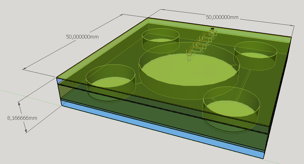
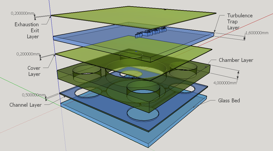
Four different chambers were designed to accommodate the four liquids involved on the biodetection process. The construction will need five layers of PDMS and one of glass, using a area of 5cmx5cm and having a height less than 1 cm.
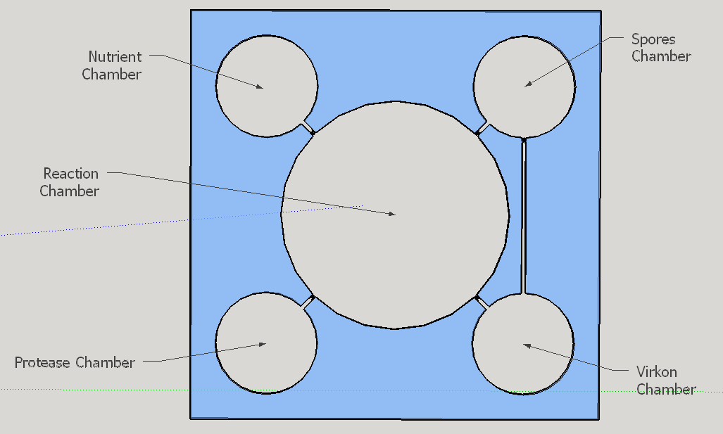
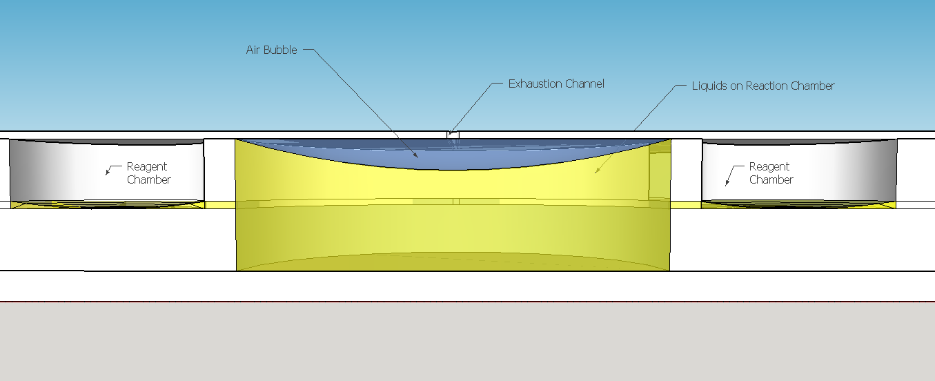
The reagent chambers and reaction chamber (see Fig. 4) are of an arbitrary volume of 522,2 microL and 3,8 mL, respectivelly. We assume that these volumes are more than enough to contain the volumes needed for flexibility in the volume proportions testing during the experiments for standarization of the chip usage.
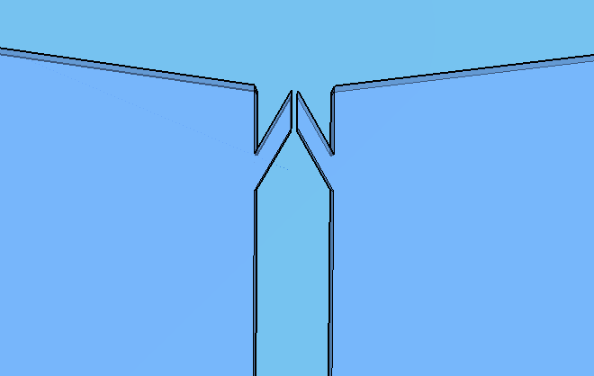
Thes connexion between the Spores and Virkon chambers (Figure 2) was necessary because of the residual spores solution that certainly will stay on the spores chamber. More information about the fluid dynamics between those chambers are below on the next subtopic at this page. To avoid the fluid flowing back to the reagent chambers, it was choosen a elegant valve that biomimics heart valves. The dimensions used are proportional from the literature data [12], in a scale of 1:4.
Because of the low pressure on the reagent chambers after the release of the membrane , the biomimic valves are supposed to close. Eventual high pressures on reaction chamber also contributes for its closing, forcing the valve corners to close the "doorway". When pressed, the PDMS "buttons" are expected to successfully expell the reagent chamber liquids to the reaction chamber. A central chamber of surplus volume is needed to hold the mixing solutions and the sample, also leaving space for a air bubble formation on the top in contact with the exhaustion channel. The reaction chamber is also a mixing chamber, where the user must press repeatedly the chamber upper part for homogenization - critical for a good visual output.
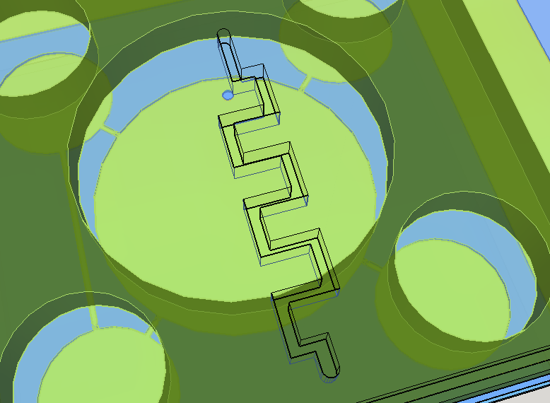
Knowing the well described turbulence profile of serpentine patterns on microfluidic chips [14], a convoluted channel was designed to trap eventual droplets that may arise from the solution mixing on the reaction chamber.
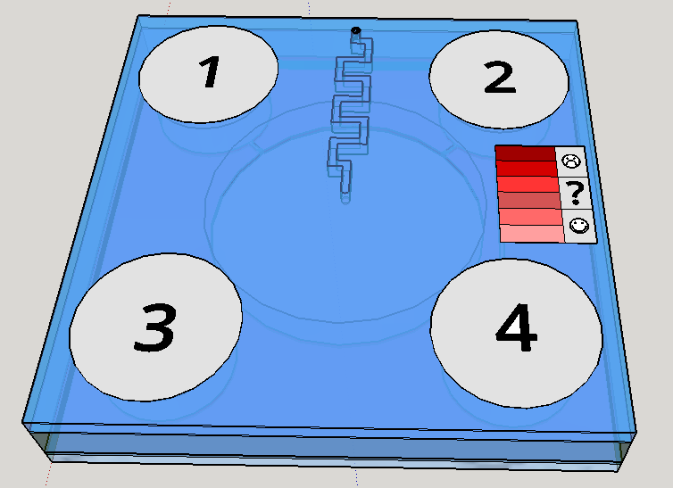
This channel structure never was used for particle trapping in the gas with droplets scenario. Further computer simulations are needed to evaluate more preciselly the hypothesis of this concept design. A syringe will be needed to fill the chambers with its respective solutions. This will be necessary to insert the blood serum sample aswell. Plastic seals will be used to cover the openings made by the needle; some of them could have numbers to indicate the order of pressing the buttons (as may be seen on Figure 1). A color scale will be provided with the device to compare the obtained output with previous standarized color results, indicating a qualitative prognostic for the user.
Given the spores germination time of about 3 hours [19], we expect a similar amount of time to our device completely provide an output. The red scale color on the Figures 1 and 8 are merely illustrative of a future approach for the project. The biological system being developed uses a fluorescent output as a proof of concept for biodetection, but the main idea ie rely the detection on a naked eye visualization and qualitative estimation.
Fluid Dynamics
To calculate the flows through the microfluidic channels, it is assumed 4 hypothesis [15]:
- The fluid "body force" is negligible;
- The influence of convection is small and also negligible;
- The flow is axiosimetric;
- The flow is stationary.
For the last hypothesis be valid, it is indirectly assumed that the button pressing movement is approximately uniform, assuring a constant pressure difference between the chambers. All this assumptions are the same used to solve the Navier-Stokes equation of fluid mechanics to find the Hagen-Poisseuille equation [18] used to describe laminar flows. In this case, there is no need to calculate the Reynolds number to estimate the flow characteristics - all the assumptions behind the Hagen-Poisseule equation already garantees that. Since we're using a 0.5 mm squared pipe, it is needed to substitute the tube diameter in the Hagen-Poisseuille equation for the equivalent hidraulic diameter[17] of a squared pipe - that is just the side of the squared section of the tube.
To estimate the pressure applied by the user, the "palmar pich" finger pressing movement was considered the most approximate movement that we expect from our user. Using an average force of almost 54 N for this type movement provided by the literature[16], we calculated a pressure of approximatedly 440 kPa to be exerted under the reagent chamber section area. Considering the tube lenght the distance from the reagent chamber to the beginning of the biomimic valve (on the valve region the laminar flow hypothesis is no more assegured) and using the viscosity of water (we estimate that the solutions will have the same order os viscosity), we have found a volumetric flow of 540 microL per second. Since the reagent chamber have almost 520 microL, it will be emptied by one second. Considering all the errors involved and the rough approximations, this is the magnitude of time appropriate for operation - our concerns were about the user need of keep holding the buttons in order to the liquid flows. The volume of Virkon to be splited on Reaction Chamber and Spores Chamber need to be proportional to the volume of spores/cells solution on each chamber. This implies in a equivalent proportional Virkon flow. We made a pessimistic estimative of the residual reagent volume on the Spore chamber, approximating the liquid surface to a spherical cap touching the spores chamber bottom (see the reagent chambers on Fig. 6). The residual volume calculated was 61.35 microL, what corresponds approximately to 9,2% of the initial volume on reagent chamber. The percentage of flow to this chamber from the Virkon chamber must be nearly to the percentage obtained to the residual volume. Calculating the volumetric flow using the same viscosity and channel section area as before, but with a tube lenght of 18,4 mm, we obtained approximately 42 microL per second, what is 7,7% of the volume flow to the reagent chamber. Since this percentage is near enough to the volume percentage lasting on the reagent chamber, we consider the connection between these reagent chambers appropriate to sanitize those compartments.
Fabrication and Tests
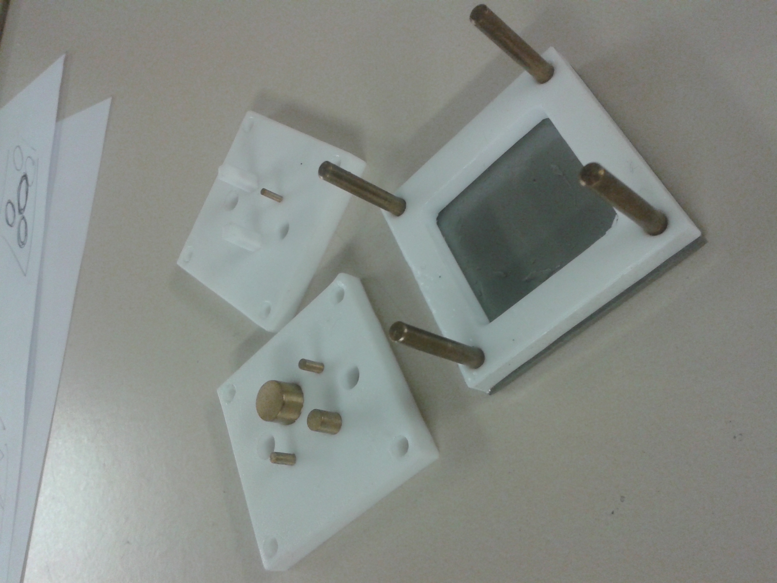
We are currently fabricating the device using PDMS photolithography technique for the thin layers and PDMS molding for the thicker ones. The molds are made from teflon structures with metal cylinders, like on the figure below:
The further results of the tests with the biomimic valve and fluid dynamics modeling will be shown in our presentation at the Jamboree. The 3D models were made using Sketchup Make, version 14 (Non commercial License). The exploded 3D model of the microfluidic device could be downloaded here. All fabrication process are being done in the [http://www.psi.poli.usp.br/index.php?p=laboratorios&s=LME&k=apresentacao Microelectronics Laboratory] in the [http://www.psi.poli.usp.br/index.php?p=departamento Department of Engineering of Electronic Systems] at the Polytechnic School of Engineering of University of São Paulo. We like to thanks [http://www.psi.poli.usp.br/index.php?p=pessoas&s=curriculo&id=2 prof. Marcelo Carreño] and the technician Alexandre Lopes from the [http://gnmd.webgrupos.com.br/ New Materials and Dispositives Research Group] for all the support and advising on microfabrication.
References:
- SACKMANN EK, FULTON AL, BEEBE DJ. The present and future role of microfluidics in biomedical research. Nature, 2014, 507.7491:181-189.
- WHITESIDES GM. The origins and the future of microfluidics. Nature, 2006, 442.7101:368-373.
- YAGER P et al. Microfluidic diagnostic technologies for global public health. Nature, 442.7101:412-418.
- http://www.pall.com/main/oem-materials-and-devices/product.page?id=46962. Accessed September 2014.
- http://www.mdimembrane.com/Products/Immunodiagnostics/Products/Rapid%20Plasma%20Separation%20Device.html. Accessed September 2014.
- WONG AP et al. Egg beater as centrifuge: isolating human blood plasma from whole blood in resource-poor settings. Lab on a Chip, 2008, 8.12:2032-2037.
- THANGWAG AL et al. An ultra-thin PDMS membrane as a bio/micro–nano interface: fabrication and characterization. Biomedical microdevices, 2007, 9.4:587-595.
- WEN CY et al. A valveless micro impedance pump driven by PZT actuation." Materials science forum. 2006. Vol. 505.
- NGE PN, ROGERS CI and WOOLEY AT. Advances in microfluidic materials, functions, integration, and applications. Chemical reviews, 2013, 113.4:2550-2583.
- MALECHA K, GANCARZ I and GOLONKA LJ. A PDMS/LTCC bonding technique for microfluidic application. Journal of Micromechanics and Microengineering, 2009, 19.10:105016.
- WIDMER AF, FREI R. Decontamination, disinfection and sterilization. In: Murray PR, Ed. Manual of Clinical Microbiology. 7th edn. Washington, DC: American Society for Microbiology, 1999, 138–164.
- OU YC et al. A passive biomimic PDMS valve applied in thermopneumatic micropump for biomicrofluidics. Nano/Micro Engineered and Molecular Systems (NEMS), 2011 IEEE International Conference on. IEEE, 2011.
- WEIBEL DB et al. Pumping fluids in microfluidic systems using the elastic deformation of poly (dimethylsiloxane). Lab on a Chip, 2007, 7.12:1832-1836.
- LIU RH et al. "Passive mixing in a three-dimensional serpentine microchannel." Journal of Microelectromechanical Systems, 2000,190-197.
- SQUIRES TM and QUAKE SR. "Microfluidics: Fluid physics at the nanoliter scale." Reviews of modern physics, 2005, 77.3:977.
- ASTIN AD. Finger force capability: measurement and prediction using anthropometric and myoelectric measures. Diss. Virginia Polytechnic Institute and State University, 1999.
- http://en.wikipedia.org/wiki/Hydraulic_diameter. Accessed September 2014.
- http://en.wikipedia.org/wiki/Hagen%E2%80%93Poiseuille_equation. Accessed September 2014.
- BLACK EP, et al. Factors influencing germination of Bacillus subtilis spores via activation of nutrient receptors by high pressure. Applied and environmental microbiology, 2005, 71.10: 5879-5887.
 "
"

