Team:EPF Lausanne/Overview
From 2014.igem.org
| Line 102: | Line 102: | ||
<div class="cntr"> | <div class="cntr"> | ||
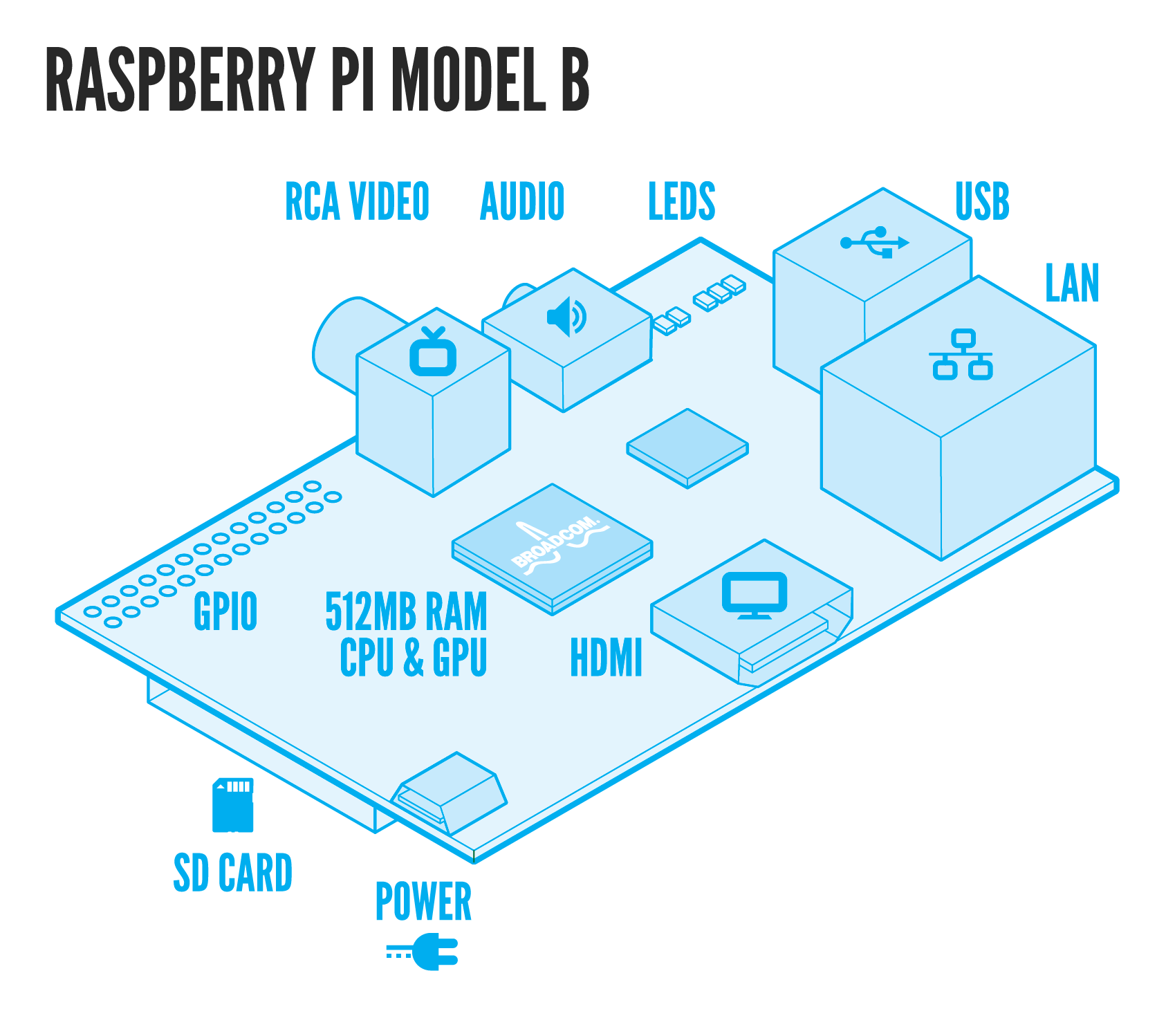
| - | <img src="http://www.raspberrypi.org/wp-content/uploads/2011/07/RaspiModelB.png" alt="first"> | + | <img src="http://www.raspberrypi.org/wp-content/uploads/2011/07/RaspiModelB.png" alt="first" width = "1000"> |
</div> | </div> | ||
Revision as of 13:21, 12 October 2014
Project
Introduction
The 2014 EPFL iGEM team has been working on showing that biologically engineered organisms can detect and process signals quickly and efficiently. With this in mind, our team brought forward a novel idea: combining Protein Complementation techniques with biosensors to achieve fast spatiotemporal analysis of bacterial or yeast response to stimuli. The 2014 EPFL iGEM team explored this hypothesis by engineering two stress related pathways in E.Coli and S.Cerevisiae with in mind the development of a BioPad: a biological touchscreen consisting of a microfluidic chip, touch responsive bacteria, and a signal detector. For more information concerning how the BioPad works click here. The pathway engineered in E.Coli, the Cpx Pathway, is a two-component regulatory system responsive to envelope stress. A full description of the pathway is available here. In S.Cerevisiae we modified the HOG Pathway - a MAPKK pathway responsive to osmotic stress. For more information concerning the HOG Pathway click here To improve the precision, safety, and quantification methods, we aimed to design custom microfluidic chips. To learn more about the microfluidic components of our project click here. Moreover, to make signal detection more practical we aimed to develop an automatised cheap tracking system made of a mini-computer (Raspberry Pi) and a mini-HD camera.

How the BioPad works
Our self-designed PDMS microfluidic chip, the BioPad, is made of hundreds of compartments representing "pixels." Each 30µm x 30µm x 3µm compartment contains a few layers of E. coli. When the surface of the chip is touched, a deformation of the chip - and thus of the compartments - leads to cellular membrane shear stress and protein aggregation/misfolding in the periplasm. The aggregated/misfolded proteins are then sensed by the histidine kinase CpxA sensor, which auto-phosphorylates and transfers its phosphate to its corresponding relay protein, CpxR. Upon phosphorylation, CpxR homo-dimerizes. Our engineered bacteria contain CpxR proteins fused to split fluorescent protein fragments (split IFP1.4) via a 10-amino acid, 2x GGGGS flexible linker. This allows us to detect CpxR dimerization, synonymous periplasmic stress and touch. Moreover, the split protein fragments are reversible. Therefore, when stress is removed, CpxA changes conformation and dephosphorylates CpxR allowing it to dissociate. The signal is shutdown and darkness returns The BioTouch Detector (composed of an inexpensive CMOS called Raspberry Pi, a highly sensitive digital camera with appropriate light filters, and a light emitting source) identifies and processes the position of the light/fluorescence emitted by the BioPad. This information about the position of the light relative to chip is then used to control the associated electronic device.


The Cpx Pathway

The natural function of the CpxA-CpxR two component regulatory system in bacteria is to control the expression of ‘survival’ genes whose products act in the periplasm to maintain membrane integrity. This ensures continued bacterial growth even in environments with harmful extracytoplasmic stresses. The CpxA-R stress pathwayThe CpxA-CpxR two component regulatory system belongs to the class I histidine kinases and includes three main proteins:

Engineering: CpxR and split complementation techniques
The main component that we wish to engineer is CpxR. It has been reported that the protein homo-dimerizes upon activation. We thus plan to use fused split proteins of fluorescent and bioluminescent nature to detect its activation.
table
As a preliminary step, we used two fluorescent proteins sfGFP and IFP to characterisation CpxR. Split sfGFP (superfolder GFP) is an irreversible split system which will be used to prove the dimerization of CpxR. Split IFP on the other hand (Infrared Fluorescent Protein) is a reversible split system which will be used to understand the spatio-temporal dimerization of CpxR and thus allow us to better understand the On/Off mechanism of this system.
To achieve our final goal, we will engineer split bioluminescent proteins: Firefly and Renilla split Luciferases. These constructs will be the main component of our system. When fused to CpxR, we are expecting to witness emission upon touch.
Engineering: Microfluidic chip interface
Our specially designed microfluidic chip, hereafter known as BioPad Chip, will allow easy and accurate induction of fluorescent or bioluminescent signals. The chip is made up of thousands of compartments – representing the pixels of our device - of the height of a bacteria. The BioTouch Chip thus allows the effective trapping and induction of stress onto our engineered bacteria.
Engineering: The BioPad Detector
The signals induced by the BioTouch Chip are then processed by our self designed detection system: the BioTouch Detector. The BioTouch Detector is mainly made of a cheap computer (Raspberry Pi), a highly sensitive digital camera with appropriate light filters, and a light emitting source. The BioTouch Detector locates signals from various sources (infrared fluorescence, green fluorescence and luminescence), processes them and sends back the relative positions of the signals with respect to the BioTouch Pad. Thanks to this position, we are able to extract information such as giving a computer operating system that the position represents the position of the mouse on a screen, that the well at the given position is a suitable antibiotic candidate, or that a gene of interest has been activated. We therefore effectively control a computer or any other electronic device through a living interface: the BioTouch Pad.
 "
"


