Team:ETH Zurich/labblog/20140528meet
From 2014.igem.org
(→Wednesday, May 28th) |
(→Wednesday, May 28th) |
||
| Line 13: | Line 13: | ||
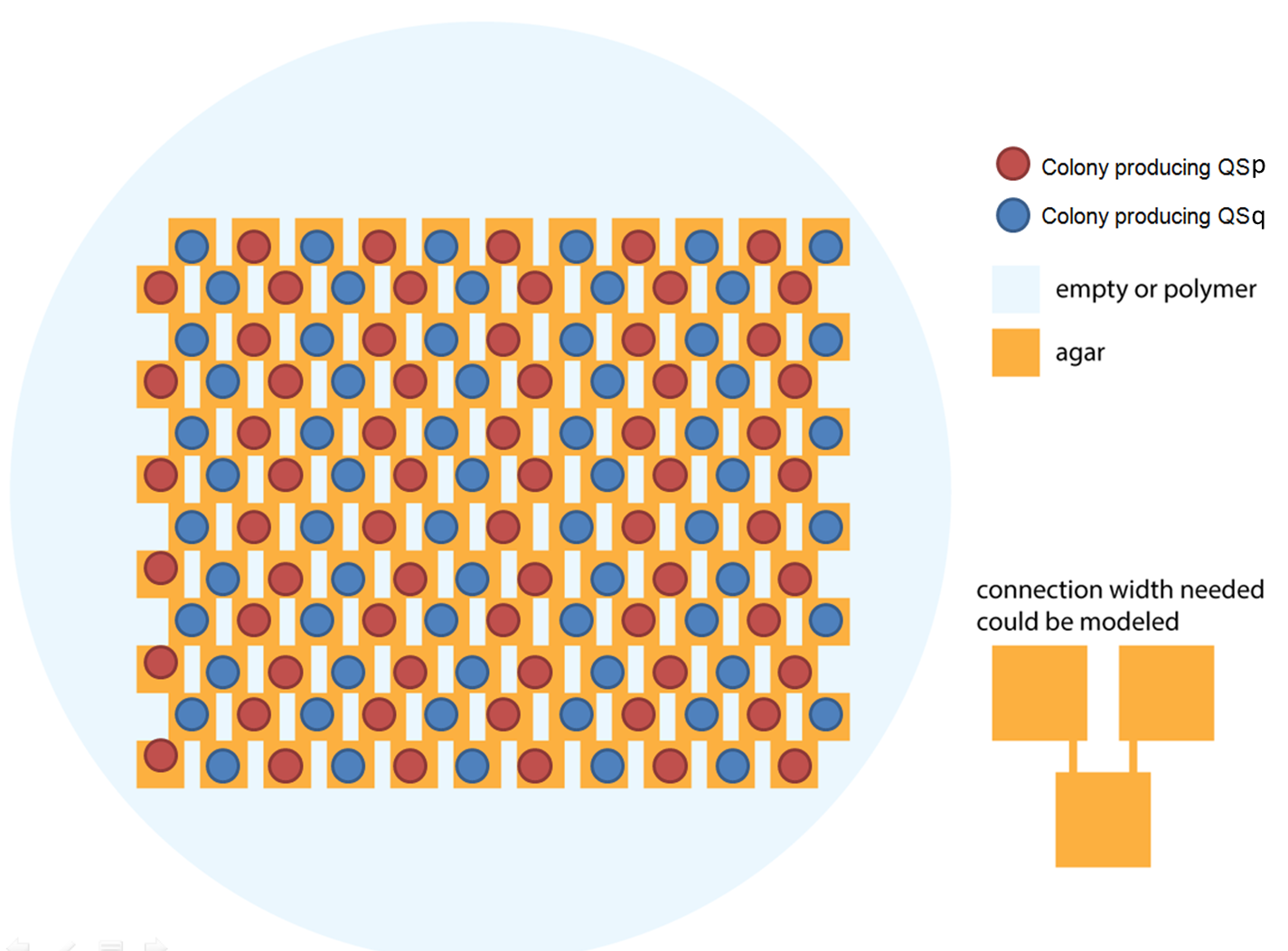
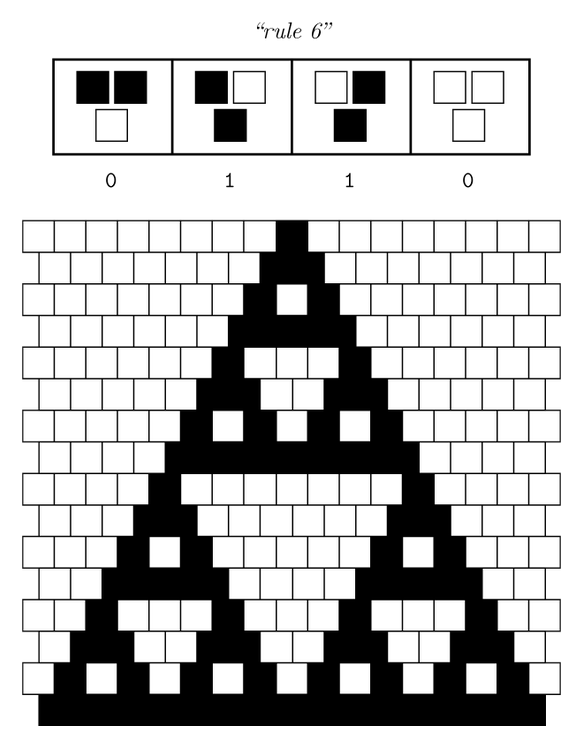
Ideally we will use a microfluidic chip. We could also use a 3D printed agar plate like this one to load the colonies. On this grid we can implement the rule 6, which is the simplification of rule 90 considered as a rule with 2 inputs : each cell computes a simple XOR gate of its two parents. | Ideally we will use a microfluidic chip. We could also use a 3D printed agar plate like this one to load the colonies. On this grid we can implement the rule 6, which is the simplification of rule 90 considered as a rule with 2 inputs : each cell computes a simple XOR gate of its two parents. | ||
| - | [[File:ETH Zurich 3Dprint agar plate.png| | + | [[File:ETH Zurich 3Dprint agar plate.png|center|600px|thumb|Arrangement of p and q cells on the chip]] |
| - | [[File:ETH Zurich Rule 6.PNG| | + | [[File:ETH Zurich Rule 6.PNG|center|300px|thumb|Pattern given by rule 6 if only one cell is switched on in the first row at the beginning. The pattern appears row by row.]] |
Revision as of 10:13, 1 September 2014
Week 1 : Project selected
Wednesday, May 28th
After more than one month of endless meetings and passionate debates, we finally chose the project that will keep us occupied in the next five months. From the beautiful pattern made by the Sierpinski triangles, we will focus on cellular automata and try to implement one.
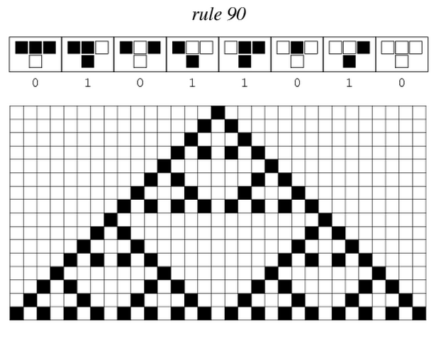
Sierpinski triangles appear when the rule 90 is followed by every cell on the grid :
Ideally we will use a microfluidic chip. We could also use a 3D printed agar plate like this one to load the colonies. On this grid we can implement the rule 6, which is the simplification of rule 90 considered as a rule with 2 inputs : each cell computes a simple XOR gate of its two parents.
The logic part will be built with integrases and the colony-to-colony communication will use quorum sensing.
Every colony will receive two quorum sensing signals (QSp and QSq) from the two cells above it. These two signals trigger the production of two different integrases r and s in the colony. Integrases enable to build biological XOR logic gates by switching twice a terminator. Indeed, every integrase can switch the terminator only once. Thus if the colony produces only r or only s, the terminator is switched only once, so the terminator is OFF, and GFP and QS1 or QS2 are produced (depending on the colony). If the colony produces r and s, the terminator is switched twice, so it is ON and it blocks expression of GFP and of the quorum sensing molecule.

We need to :
- find orthogonal quorum sensing molecules and orthogonal integrases
- discuss with microfluidics experts to check if using microfluidics is possible and presents advantages in our case
- find possible parts in the registry for integrases, and design plasmids
 "
"


