 "
"
Team:TU Delft-Leiden/Modeling/Curli
From 2014.igem.org
| (134 intermediate revisions not shown) | |||
| Line 3: | Line 3: | ||
{{:Team:TU_Delft-Leiden/Templates/Start}} | {{:Team:TU_Delft-Leiden/Templates/Start}} | ||
| - | |||
<html> | <html> | ||
<body> | <body> | ||
<div class='grid_12'> | <div class='grid_12'> | ||
| - | + | ||
<h2> Curli Module</h2> | <h2> Curli Module</h2> | ||
<p> | <p> | ||
| - | The goal of our project for the conductive curli module is to produce a biosensor that consists of <i>E. coli</i> that are able to build a conductive biofilm, induced by any promoter, | + | The goal of our project for the conductive curli module is to produce a biosensor that consists of <i>E. coli</i> that are able to build a conductive biofilm, induced by any promoter, see the <a href="https://2014.igem.org/Team:TU_Delft-Leiden/Project/Gadget">gadget section</a> of our wiki and the <a href="https://2014.igem.org/Team:TU_Delft-Leiden/Project/Life_science/EET">extracellular electron transport (EET) module</a>. The biofilm consists of curli containing His-tags that can connect to gold nanoparticles, see the <a href="https://2014.igem.org/Team:TU_Delft-Leiden/Project/Life_science/curli">conductive curli module</a>. When the curli density is sufficiently high, a dense network of connected curli fibrils is present around the cells. Further increasing the amount of curli results in a conductive pathway connecting the cells, thereby forming conductive clusters. Increasing the amount of curli even further, sufficiently curli fibrils are present to have a cluster that connects the two electrodes and thus have a conducting system. <br> |
| - | The goal of the modeling of the curli module is to prove that our biosensor system works as expected and to capture the dynamics of our system. So, we want to answer the question: "Does a conductive path between the two electrodes arise at a certain point in time?" However, we not only want to answer the question if our system works as expected qualitatively, but we also want to make quantitative predictions about the | + | The goal of the modeling of the curli module is to prove that our biosensor system works as expected and to capture the dynamics of our system. So, we want to answer the question: "Does a conductive path between the two electrodes arise at a certain point in time and at which time does this happen?" However, we not only want to answer the question if our system works as expected qualitatively, but we also want to make quantitative predictions about the resistance between the two electrodes of our system in time. |
</p> | </p> | ||
| - | |||
| - | |||
| - | |||
| - | |||
| - | |||
| - | |||
| - | |||
| - | |||
| - | |||
| - | |||
| - | |||
| - | |||
| - | |||
| - | |||
| - | |||
| - | |||
| - | |||
| - | |||
| - | |||
| - | |||
| - | |||
| - | |||
| - | |||
| - | |||
| - | |||
| - | |||
| - | |||
| - | |||
| - | |||
| - | |||
| - | |||
| - | |||
| - | |||
| - | |||
| - | |||
| - | |||
| - | |||
| - | |||
| - | |||
| - | |||
<div class="tableofcontents"> | <div class="tableofcontents"> | ||
| - | < | + | <ul> <p> Curli Module </p> |
| - | |||
| - | |||
| - | |||
| - | |||
| - | |||
| - | |||
<ul> | <ul> | ||
<li> | <li> | ||
| - | <a href="/Team:TU_Delft-Leiden/Modeling/Curli | + | <a href="https://2014.igem.org/Team:TU_Delft-Leiden/Modeling/Curli/Gene"> |
<p>Gene Level Modeling</p> | <p>Gene Level Modeling</p> | ||
</a> | </a> | ||
<ul> | <ul> | ||
<li> | <li> | ||
| - | <a href="https://2014.igem.org/Team:TU_Delft-Leiden/Modeling/Curli#extendedgenelevel"> | + | <a href="https://2014.igem.org/Team:TU_Delft-Leiden/Modeling/Curli/Gene#extendedgenelevel"> |
<p>Extensive Gene Level Modeling</p> | <p>Extensive Gene Level Modeling</p> | ||
</a> | </a> | ||
| Line 82: | Line 35: | ||
<li> | <li> | ||
| - | <a href="https://2014.igem.org/Team:TU_Delft-Leiden/Modeling/Curli#simplifiedgenelevel"> | + | <a href="https://2014.igem.org/Team:TU_Delft-Leiden/Modeling/Curli/Gene#simplifiedgenelevel"> |
<p>Simplified Gene Level Modeling</p> | <p>Simplified Gene Level Modeling</p> | ||
</a> | </a> | ||
| Line 90: | Line 43: | ||
<li> | <li> | ||
| - | <a href="/Team:TU_Delft-Leiden/Modeling/Curli | + | <a href="https://2014.igem.org/Team:TU_Delft-Leiden/Modeling/Curli/Cell"> |
<p>Cell Level Modeling</p> | <p>Cell Level Modeling</p> | ||
</a> | </a> | ||
<ul> | <ul> | ||
<li> | <li> | ||
| - | <a href="https://2014.igem.org/Team:TU_Delft-Leiden/Modeling/Curli#discretization"> | + | <a href="https://2014.igem.org/Team:TU_Delft-Leiden/Modeling/Curli/Cell#discretization"> |
<p>Discretization of Gene Level Model</p> | <p>Discretization of Gene Level Model</p> | ||
</a> | </a> | ||
| Line 101: | Line 54: | ||
<li> | <li> | ||
| - | <a href="https://2014.igem.org/Team:TU_Delft-Leiden/Modeling/Curli#building"> | + | <a href="https://2014.igem.org/Team:TU_Delft-Leiden/Modeling/Curli/Cell#building"> |
<p>Building the Curli Fibrils</p> | <p>Building the Curli Fibrils</p> | ||
</a> | </a> | ||
| Line 107: | Line 60: | ||
<li> | <li> | ||
| - | <a href="https://2014.igem.org/Team:TU_Delft-Leiden/Modeling/Curli#conductiveradius"> | + | <a href="https://2014.igem.org/Team:TU_Delft-Leiden/Modeling/Curli/Cell#FittingCurliDensity"> |
| + | <p>Fitting the Curli Density</p> | ||
| + | </a> | ||
| + | </li> | ||
| + | |||
| + | <li> | ||
| + | <a href="https://2014.igem.org/Team:TU_Delft-Leiden/Modeling/Curli/Cell#conductiveradius"> | ||
<p>Conductive Radius of the Cell</p> | <p>Conductive Radius of the Cell</p> | ||
</a> | </a> | ||
| Line 115: | Line 74: | ||
<li> | <li> | ||
| - | <a href="/Team:TU_Delft-Leiden/Modeling/Curli | + | <a href="https://2014.igem.org/Team:TU_Delft-Leiden/Modeling/Curli/Colony"> |
<p>Colony Level Modeling</p> | <p>Colony Level Modeling</p> | ||
</a> | </a> | ||
<ul> | <ul> | ||
<li> | <li> | ||
| - | <a href="https://2014.igem.org/Team:TU_Delft-Leiden/Modeling/Curli#percolation"> | + | <a href="https://2014.igem.org/Team:TU_Delft-Leiden/Modeling/Curli/Colony#percolation"> |
<p>Percolation</p> | <p>Percolation</p> | ||
</a> | </a> | ||
| Line 126: | Line 85: | ||
<li> | <li> | ||
| - | <a href="https://2014.igem.org/Team:TU_Delft-Leiden/Modeling/Curli#resistivity"> | + | <a href="https://2014.igem.org/Team:TU_Delft-Leiden/Modeling/Curli/Colony#resistivity"> |
| - | <p> | + | <p>Resistance</p> |
| + | </a> | ||
| + | </li> | ||
| + | <li> | ||
| + | <a href="https://2014.igem.org/Team:TU_Delft-Leiden/Modeling/Curli/Colony#recommendations"> | ||
| + | <p>Recommendations for product design and wet lab</p> | ||
</a> | </a> | ||
</li> | </li> | ||
</ul> | </ul> | ||
| + | <li> | ||
| + | <a href="https://2014.igem.org/Team:TU_Delft-Leiden/Modeling/Curli/Reflection"> | ||
| + | <p>Critical Reflection on our Model</p> | ||
| + | </a> | ||
| + | </li> | ||
</li> | </li> | ||
</ul> | </ul> | ||
| - | + | </ul> | |
| - | + | ||
| - | </ul> | + | |
| - | + | ||
</div> | </div> | ||
| - | |||
| - | |||
| - | |||
| - | |||
| - | |||
| - | |||
| - | |||
| - | |||
| - | |||
<br> | <br> | ||
| - | |||
| - | |||
| - | |||
<p> | <p> | ||
| - | < | + | To capture the dynamics of our system, we have implemented a three-layered model, consisting of the gene level layer, the cell level layer and the colony level layer: |
| + | <ul> | ||
| + | <li> | ||
| + | At the gene level, we calculate the curli subunits production rates and curli subunit growth that will be used in the cell level. | ||
| + | </li> | ||
| + | <li> | ||
| + | At the cell level, we use these production and growth rates to calculate the curli growth in time, which we will use at the colony level. | ||
| + | </li> | ||
| + | <li> | ||
| + | At the colony level layer, we determine if our system works as expected, ie. determine if a conductive path between the two electrodes arises at a certain point in time and at which time this happens. We also determine the change of the resistance between the two electrodes of our system in time. | ||
| + | </li> | ||
| + | </ul> | ||
</p> | </p> | ||
| - | |||
| - | |||
| - | |||
| - | |||
| - | |||
<p> | <p> | ||
| - | + | A figure of our three-layered model is displayed below. | |
| - | + | ||
</p> | </p> | ||
| - | |||
| - | |||
| - | |||
| - | |||
| - | |||
| - | |||
| - | |||
| - | |||
| - | |||
| - | |||
| - | |||
| - | |||
| - | |||
| - | |||
| - | |||
| - | |||
| - | |||
| - | |||
| - | |||
| - | |||
| - | |||
| - | |||
| - | |||
| - | |||
| - | |||
| - | |||
| - | |||
| - | |||
| - | |||
| - | |||
| - | |||
| - | |||
| - | |||
| - | |||
| - | |||
| - | |||
| - | |||
| - | |||
| - | |||
| - | |||
| - | |||
| - | |||
| - | |||
| - | |||
| - | |||
| - | |||
| - | |||
| - | |||
| - | |||
| - | |||
| - | |||
| - | |||
| - | |||
| - | |||
| - | |||
| - | |||
| - | |||
| - | |||
| - | |||
| - | |||
| - | |||
| - | |||
| - | |||
| - | |||
| - | |||
| - | |||
| - | |||
| - | |||
| - | |||
| - | |||
| - | |||
| - | |||
| - | |||
| - | |||
| - | |||
| - | |||
| - | |||
| - | |||
| - | |||
| - | |||
| - | |||
| - | |||
| - | |||
| - | |||
| - | |||
| - | |||
| - | |||
| - | |||
| - | |||
| - | |||
| - | |||
| - | |||
| - | |||
| - | |||
| - | |||
| - | |||
| - | |||
| - | |||
| - | |||
| - | |||
| - | |||
| - | |||
| - | |||
| - | |||
| - | |||
| - | |||
| - | |||
| - | |||
| - | |||
| - | |||
| - | |||
| - | |||
| - | |||
| - | |||
| - | |||
| - | |||
| - | |||
| - | |||
| - | |||
| - | |||
| - | |||
| - | |||
| - | |||
| - | |||
| - | |||
| - | |||
| - | |||
| - | |||
| - | |||
| - | |||
| - | |||
| + | <h3>Click in the figure to move to the corresponding page.</h3> | ||
<figure> | <figure> | ||
| - | <img src="https://static.igem.org/mediawiki/2014/ | + | <img src="https://static.igem.org/mediawiki/2014/f/fa/TU_Delft_2014_ModellingFigureCurli_small.png" width="800" height="920" usemap="#ModelMap"> |
| - | + | ||
| - | + | ||
| - | + | ||
| - | + | ||
| - | < | + | <map name="ModelMap"> |
| + | <area shape="rect" coords="0,0,800,296" href="https://2014.igem.org/Team:TU_Delft-Leiden/Modeling/Curli/Gene" alt="Gene level"> | ||
| + | <area shape="rect" coords="0,296,800,592" href="https://2014.igem.org/Team:TU_Delft-Leiden/Modeling/Curli/Cell" alt="Cell level"> | ||
| + | <area shape="rect" coords="0,592,800,920" href="https://2014.igem.org/Team:TU_Delft-Leiden/Modeling/Curli/Colony" alt="Colony level"> | ||
| - | + | </map> | |
| - | + | ||
| - | + | ||
| - | |||
| - | |||
<figcaption> | <figcaption> | ||
| - | Figure | + | Figure 1: A schematic view of our model, which is a three-layered model. Each layer determines characteristic parameters for the layer above it. At the gene level, we calculate the curli subunits production rates. At the cell level, we use these production rates to calculate the curli growth in time. At the colony level, we use the curli growth in time to determine the change of the resistance between the two electrodes of our system in time. |
</figcaption> | </figcaption> | ||
</figure> | </figure> | ||
| Line 322: | Line 146: | ||
<br> | <br> | ||
| - | |||
| - | |||
| - | |||
| - | |||
| - | |||
| - | |||
| - | |||
| - | |||
<p> | <p> | ||
| - | < | + | We start with the modeling of the gene expression of proteins involved in the curli formation pathway at the gene level. In the constructs we made in the wet lab, CsgA is continuously being produced and the CsgB gene is placed under the control of a landmine promoter, activated by either TNT or DNT, see the <a href="https://2014.igem.org/Team:TU_Delft-Leiden/WetLab/landmine">Landmine Detection Module</a>. So, when the cells get induced by TNT or DNT, CsgB protein production will get started and CsgA will already be present in the system, as CsgA is continuously being produced. We first modeled this system by constructing an extensive gene expression model of the curli formation pathway. Subsequently, we simplified this model, so less parameters were needed. <br> |
| - | </p> | + | Based on the simplified model, we made a plot of the curli growth as function of time for different initial concentrations of \(CsgA_{free}\), see figure 2. We conclude the following from this figure: </p> |
| - | |||
| - | |||
| - | |||
| - | |||
| - | |||
| - | |||
| - | |||
<ul> | <ul> | ||
<li> | <li> | ||
| - | + | Firstly, as expected, curli growth stabilizes to a rate equal to \(p_{A}\) after approximately 2 hours, independent of the initial concentration of \(CsgA_{free}\). The width of this peak is determined by the product \( k p_B\), where k is the production rate of curli and \( p_B\) is the production rate of CsgB proteins. | |
</li> | </li> | ||
| - | <li> | + | <li> |
| - | + | Secondly, increasing the initial concentration of \(CsgA_{free}\), increases the height of the peak. Even with zero initial \(CsgA_{free}\) concentration, a small peak can be found at one hour. This is a consequence of \(CsgA_{free}\) build-up when the CsgB concentration is still very small. | |
</li> | </li> | ||
| - | <li> | + | <li> |
| - | + | Thirdly, during the first two hours, few CsgB proteins are present in the system. We therefore expect that the length of the curli fibrils that started in the first few hours are much longer than the fibrils that started at later times. | |
</li> | </li> | ||
| - | </ul | + | </ul> |
| - | + | ||
| - | < | + | <figure> |
| + | <img src="https://static.igem.org/mediawiki/2014/e/e9/Delft2014_DifferentA0.png" width="60%" height="60%"> | ||
| + | <figcaption> | ||
| + | Figure 2: The curli subunit growth in units per second for various initial concentrations \( A_0 \) of CsgA as function of time. Initial concentrations that equal 0, 5, 10 or 15 hours of CsgA production are shown. | ||
| + | </figcaption> | ||
| + | </figure> | ||
| - | |||
| - | |||
| - | |||
| - | |||
| - | |||
| - | |||
| - | |||
| - | |||
<br> | <br> | ||
| - | |||
| - | |||
<p> | <p> | ||
| - | + | Using the growth rate of curli and production of CsgB protein as function of time obtained from the gene level model, the conductance as a function of time can be computed for the cell. We obtained an analytical expression for \(\rho_{curli}\), which represents the density of curli fibrils around the cell. We have fitted the function | |
| - | + | $$ \rho_n = C_{1_n} e^{-\frac{r}{C_{2_n}}} + C_{3_n} e^{-\frac{r}{C_{4_n}}} \tag{1}$$ | |
| - | + | to our curli density curves at each time \( n \), see figure 3 the red line. At first, we tried to fit our data to only one exponential term (green line). It can clearly be seen in the figure that this does not adequately capture the dynamics of the curve. However, equation 1 gives a very good fit to the curli density curves at each time \( n \). The reason for fitting such a simple function is that, in the colony level, we need to quantify the conductance between the cells. The integral for this rather complicated and we need an analytical function for \(\rho_{curli}\) to analytically solve this integral. <br> | |
| - | + | We also calculated the conductive radius of the cell as a function of the radius, see figure 4. The conductive radius is the largest radius where \(\rho_{curli}\) is bigger than a certain threshold of curli density. We use the conductive radius in the colony level to determine when a conductive path between the two electrodes of our system arises. | |
| - | + | ||
| - | + | ||
| - | + | ||
| - | + | ||
| - | + | ||
| - | + | ||
| - | + | ||
| - | + | ||
| - | + | ||
| - | + | ||
| - | + | ||
| - | + | ||
| - | + | ||
| - | + | ||
| - | + | ||
| - | + | ||
| - | + | ||
| - | + | ||
| - | + | ||
| - | <br> | + | |
| - | + | ||
| - | + | ||
| - | + | ||
</p> | </p> | ||
<figure> | <figure> | ||
| - | <img src="https://static.igem.org/mediawiki/2014/ | + | <img src="https://static.igem.org/mediawiki/2014/3/3f/TUDelft_2014_FittingCurli.png" width="60%" height="60%"> |
<figcaption> | <figcaption> | ||
| - | Figure 3: | + | Figure 3: Blue line: Right behind the red line, at t=5 hr the mean of all density curves. Green line: a weighted fit of \( \rho_n = C_{1_n} e^{-\frac{r}{C_{2_n}}} \). Red line: A fit \( \rho_n = C_{1_n} e^{-\frac{r}{C_{2_n}}} + C_{3_n} e^{-\frac{r}{C_{4_n}}} \) to the blue line. |
</figcaption> | </figcaption> | ||
</figure> | </figure> | ||
<br> | <br> | ||
| - | |||
| - | |||
| - | |||
| - | |||
<figure> | <figure> | ||
| - | <img src="https://static.igem.org/mediawiki/2014/ | + | <img src="https://static.igem.org/mediawiki/2014/e/e1/TUDelft_2014_cellradius.png" width="60%" height="60%"> |
<figcaption> | <figcaption> | ||
| - | Figure 4: | + | Figure 4: The green lines are the conductive radius plotted versus the time for 100 cells with a critical density of \( \rho_{crit}=1204 \) curli subuntis \( \mu m ^{-3} \). The orange red represents the mean conductive radius and the dark blue lines represent two standard deviations from the mean. |
</figcaption> | </figcaption> | ||
</figure> | </figure> | ||
| Line 424: | Line 200: | ||
<p> | <p> | ||
| - | + | An illustrative view of what our cell looks like during the adding of curli subunits is shown in figure 5. | |
</p> | </p> | ||
| - | |||
| - | |||
| - | |||
| - | |||
| - | < | + | <figure> |
| - | < | + | <img class="theimage" src="https://static.igem.org/mediawiki/2014/e/e3/TU_Delft_2014_Curli_picturestill.png" alt="meh" width="60%" height="60%"/> |
| - | + | <img class="theimage2 hidden" src="https://static.igem.org/mediawiki/2014/3/37/TU_Delft_2014_Curli_picture.gif" alt="meh" width="60%" height="60%"/> | |
| - | + | ||
| - | + | ||
| - | + | ||
| - | <img src="https://static.igem.org/mediawiki/2014/ | + | |
<figcaption> | <figcaption> | ||
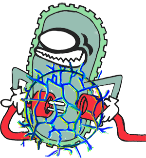
| - | Figure | + | Figure 5: Schematic view of our cell (black sphere centred at x=y=z=0) with growing curli fibrils. The wires represent the curli fibrils. <b> Click to play!</b> |
</figcaption> | </figcaption> | ||
</figure> | </figure> | ||
| + | <script> | ||
| + | $(".theimage").click(function() { | ||
| + | $(this).addClass('hidden'); | ||
| + | $(this).next().removeClass('hidden'); | ||
| + | }); | ||
| + | $(".theimage2").click(function() { | ||
| + | $(this).addClass('hidden'); | ||
| + | $(this).prev().removeClass('hidden'); | ||
| + | }); | ||
| + | </script> | ||
<br> | <br> | ||
| - | |||
| - | |||
| - | |||
| - | + | <p> | |
| - | + | Now that we determined values for \(\rho_{curli}\) and \(r_{cond}\) at the cell level, we can finally predict if our system works as expected and capture the dynamics of our system. Firstly, we want to prove that our system works as expected. So, we want to predict if a conductive path between the two electrodes arise at a certain point in time and at which time this happens. Secondly, we not only want to answer the question if our system works as expected with a yes or no answer, but we also want to make quantitative predictions about the resistance between the two electrodes of our system in time. We do this by modeling the curli growth on the colony level; each cell is now visualized and has curli growth. Now, we have come up with two different approaches:<ul> | |
| - | + | ||
| - | + | ||
| - | + | ||
| - | <p> | + | |
| - | + | ||
| - | <ul> | + | |
<li> | <li> | ||
| - | + | Firstly, we let the cells increase their conductive radius in time, according with our findings on the cellular level (figure 4). A connection is created from one electrode to the other electrode when there is a conductive path between them. Conductive paths consists of cells that have a connection between each other; cells connect when there is an overlap between their conductive radius. This problem is very similar to problems in <a href="https://2014.igem.org/Team:TU_Delft-Leiden/Modeling/Techniques#PercolationTheory">percolation theory</a>. From this, we can make conclusions about how our system works in an experimental setting. | |
</li> | </li> | ||
<li> | <li> | ||
| - | + | Secondly, we also want to make quantitative predictions about the resistance between the two electrodes of our system in time. Therefore, we used <a href="https://2014.igem.org/Team:TU_Delft-Leiden/Modeling/Techniques#GraphTheory">graph theory</a> to translate the cells on the chip to a graph and used an algorithm from graph theory to calculate the resistance between the two electrodes. The conductance between the cells is computed from an integral and is equal to: | |
| - | + | $$ \sigma (y) = \ 2 \pi \left( C_{1}^2 C_2 e^{-\frac{y}{C_2}} + C_{3}^2 C_4 e^{-\frac{y}{C_4}} + \frac{4 C_{1}C_3 C_2^2 C_4^2}{y \left( C_2^2 - C_4^2 \right)} \left( e^{-\frac{y}{C_2}} -e^{-\frac{y}{C_4}} \right) \right) \tag{1}$$ | |
| - | + | ||
| - | + | ||
</li> | </li> | ||
</ul> | </ul> | ||
</p> | </p> | ||
| - | |||
| - | |||
| - | |||
| - | |||
| - | |||
| - | |||
| - | |||
<br> | <br> | ||
<p> | <p> | ||
| - | + | Using the first approach, a simulation of our resulting model is shown in figure 6. Percolation is computed by applying an algorithm that can find clusters of connected cells. When one of the clusters connects both electrodes, there is percolation. | |
| - | + | ||
</p> | </p> | ||
| + | |||
<figure> | <figure> | ||
| - | <img src="https://static.igem.org/mediawiki/2014/ | + | |
| + | <img class="theimage" src="https://static.igem.org/mediawiki/2014/1/1d/TU_Delft_2014_model_curli_colony_static.png" alt="meh" width="60%" height="60%"/> | ||
| + | <img class="theimage2 hidden" src="https://static.igem.org/mediawiki/2014/9/9f/TU_Delft_2014_model_curli_colony.gif" alt="meh" width="60%" height="60%"/> | ||
<figcaption> | <figcaption> | ||
| - | Figure | + | Figure 6: NorthWest: A visual representation of our cells on the plate. The circles represent the cells with an increasing conductive radius. In this simulation there are 5000 cells present on a chip of 500µmx500µm. NorthEast: A spy matrix of 5000x5000 where the blue dots represent connections between the individual cells. A blue dot on position x,y means that cell x is connected with y. Each cell is connected to itself (diagonal). At the point of percolation, \( \approx 0.1 \% \) of the matrix is connected, meaning that each cell is on average connected to 5 others. SouthWest: Each square of nxn represents a cluster of n connected cells. The squares are sorted from small to large. SouthEast: This figure shows the largest cluster of cells in different colors. <b> Click to play!</b> |
</figcaption> | </figcaption> | ||
</figure> | </figure> | ||
| + | <script> | ||
| + | $(".theimage").click(function() { | ||
| + | $(this).addClass('hidden'); | ||
| + | $(this).next().removeClass('hidden'); | ||
| + | }); | ||
| + | $(".theimage2").click(function() { | ||
| + | $(this).addClass('hidden'); | ||
| + | $(this).prev().removeClass('hidden'); | ||
| + | }); | ||
| + | </script> | ||
<br> | <br> | ||
<p> | <p> | ||
| - | + | We simulated our resulting model 100 times and for each point in time we checked the chance of percolation without variation in \(r_{cond}\) (yellow line in figure 7) and with cellular variation in \(r_{cond}\) (blue line in figure 7). Fortunately, the blue and yellow lines are very similar. This means that cellular variation has little influence on the chance of percolation at each point in time. Therefore, the results of our model are robust to cellular variation and it is likely that many factors that could increase the cellular variation, e.g. different CsgA or CsgB protein production rates, are relatively unimportant. | |
</p> | </p> | ||
| - | + | <img src="https://static.igem.org/mediawiki/2014/d/dc/TUDelft_2014_500x500ChipResults.png" width="60%" height="60%"> | |
| - | + | ||
| - | <img src="https://static.igem.org/mediawiki/2014/ | + | |
<figcaption> | <figcaption> | ||
| - | Figure | + | Figure 7: The chance of percolation with 5000 cells on a 500x500 \(\mu m \) chip. as function of time. The results are from 100 simulations. The yellow line represents the chance of percolation where all the cells have the same conductive radius. The blue line is the same simulation, but all cells have slightly different conductive radii. Note how there is no notable difference between the two. |
</figcaption> | </figcaption> | ||
</figure> | </figure> | ||
| Line 510: | Line 280: | ||
<p> | <p> | ||
| - | + | As we want our system to be usable as a biosensor, it has to be strongly dependent on the analyte concentration, and therefore the CsgB production rate. From figure 8, we see that there are very distinguishable difference for different CsgB production rates. First of all, the moment of percolation differs a lot. Equally important, the transition from no percolation to percolation is much less sharper. | |
</p> | </p> | ||
| + | |||
<figure> | <figure> | ||
| - | <img src="https://static.igem.org/mediawiki/2014/ | + | <img src="https://static.igem.org/mediawiki/2014/0/02/TUDelft2014_Percolation_InductionDifferences.png" width="60%" height="60%"> |
<figcaption> | <figcaption> | ||
| - | Figure | + | Figure 8: The change of induction for t=0:10 hours, when cellular differences are included in the cell level for different induction strengths. The orange line is created by reducing the promoter strength of the cyan line (\(p_B = 1.3 \cdot 10^{-13} M/s \) ) by 50%. |
</figcaption> | </figcaption> | ||
</figure> | </figure> | ||
<br> | <br> | ||
| + | |||
<p> | <p> | ||
| - | + | Using the second approach, we have calculated the conductance as function of time for different dimensions of our plate. We varied the distance between the electrodes between 210, 460 and 960 \( \mu m \). The length of the electrodes is kept at \( 500 \mu m\). The result is shown in figure 9. | |
</p> | </p> | ||
| + | |||
<figure> | <figure> | ||
| - | <img src="https://static.igem.org/mediawiki/2014/ | + | <img src="https://static.igem.org/mediawiki/2014/c/c5/TUDelft2014_Colony_DifferentSizes.png" width="60%" height="60%"> |
<figcaption> | <figcaption> | ||
| - | Figure | + | Figure 9: The conductance of our system as function of time, using the results from the gene and the colony level. Different simulations have been done with different chip sizes. The length of the chips is in all cases \( 500 \mu m \). The distance between the electrodes is varied from \( 210 \mu m \) (green lines) to \( 460 \mu m \) (red lines) and \( 960 \mu m \) (blue lines). There are multiple lines for the green and red lines as we repeated the simulations multiple times. However the simulation for when the electrodes were \( 960 \mu m \) apart was only performed once. |
</figcaption> | </figcaption> | ||
</figure> | </figure> | ||
| Line 536: | Line 309: | ||
<p> | <p> | ||
| - | + | Another parameter we investigated is the influence of cell density on the conductivity of the system. From percolation theory we have learned that this has a strong influence on the moment of percolation. The results are shown in figure 10. | |
</p> | </p> | ||
| - | |||
| - | |||
| - | |||
| - | |||
| - | |||
| - | |||
| - | |||
| - | |||
| - | |||
| - | |||
| - | |||
| - | |||
| - | |||
| - | |||
| - | |||
| - | |||
| - | |||
| - | |||
| - | |||
| - | |||
| - | |||
| - | |||
| - | |||
| - | |||
| - | |||
| - | |||
| - | |||
| - | |||
| - | |||
| - | |||
| - | |||
<figure> | <figure> | ||
| - | <img src="https://static.igem.org/mediawiki/2014/ | + | <img src="https://static.igem.org/mediawiki/2014/f/ff/TUDelft2014_Colony_CellDens.png" width="60%" height="60%"> |
<figcaption> | <figcaption> | ||
| - | Figure | + | Figure 10: The conductance of our chip ( \( 500\mu m \ by \ 500\mu m \) as function of time. Two different cell densities have been simulated. The red lines show simulations with a cell density of \( 2 \cdot 10^4 cells / mm^2\). The blue lines show the results with a cell density of \( 2.4 \cdot 10^4 cells / mm^2\) |
</figcaption> | </figcaption> | ||
</figure> | </figure> | ||
| Line 580: | Line 322: | ||
<p> | <p> | ||
| - | + | The most important question of all is: Will our system work, and under what conditions? To answer this question we have done the exact same simulation for the gene level and the cell level as elsewhere, except with the only difference that we halved the promoter strength of CsgB. This simulates less CsgB protein production, which corresponds to less TNT/DNT present in the system. The results are shown in figure 11. | |
| - | + | ||
</p> | </p> | ||
<figure> | <figure> | ||
| - | <img src="https://static.igem.org/mediawiki/2014/ | + | <img src="https://static.igem.org/mediawiki/2014/6/6d/TUDelft2014_Colony_ActivationStrength.png" width="60%" height="60%"> |
<figcaption> | <figcaption> | ||
| - | Figure | + | Figure 11: The conductance of our chip ( \( 500\mu m \ by \ 500\mu m \) as function of time. Two different activation strengths have been simulated. The red lines (same as in figure 6 and 7) show a 100% activated CsgB promoter. The blue lines show the results for a promoter that is activated for 50%.</figcaption> |
| - | </figcaption> | + | |
</figure> | </figure> | ||
<br> | <br> | ||
| - | |||
| - | |||
<p> | <p> | ||
| - | + | Based on the above three figures, there are a couple of recommendations we have for the design of the chip: | |
| - | + | <ul> | |
| - | < | + | <li> |
| - | + | Based on figure 9, we recommend to decrease the distance between the electrodes. This will increase the conductance without increasing the uncertainty. From the shape of the curve, we expect that we do not have to wait very long (only a couple of hours) to do a measurement. After a steep increase in conductance, the increase in conductance will be relatively small in time. Furthermore, the uncertainty due to the placement of our cells increases in time. | |
| - | + | </li> | |
| - | + | <li> | |
| - | < | + | Based on figure 10, we recommend high cell density for increased signal strength of our system. However, it is crucial that the cell density is kept constant throughout the measurement. Cell density influences the conductance significantly and when the cell density is not kept constant, it will influence the conductance measurements in such a way that an increase or decrease in conductance can not only be attributed to an increase or decrease in DNT any longer. |
| - | + | </li> | |
| - | </ | + | <li> |
| - | + | From figure 11, we learned that we have to be very careful with our measurement time in order to be able to draw conclusions about the concentration of TNT/DNT. The influence of the induction strength of the CsgB promoter is very small and its influence decreases after the initial amount of CsgA protein have formed curli. A recommendation for the wet lab is to increase the waiting time prior to induction of the promoter and thereby increasing the initial amount of CsgA protein. This will increase the relative differences in conductance between different induction strengths of the CsgB promoter. In our model, this increase in relative differences in conductance happens between 0 and 2.5 hours. <br> | |
| - | + | The time this increase in relative differences in conductance happens, is strongly dependent on the parameter k in our <a href="https://2014.igem.org/Team:TU_Delft-Leiden/Modeling/Curli/Gene#simplifiedgenelevel">simplified gene model</a>. For our model, we could fit this parameter to conductance curves obtained in the wet lab. Measuring conductance until observing a linear increase in time will give the most useful information for obtaining the inducer concentration, as the time of this transition depends on the strength of induction. | |
| - | + | </li> | |
| - | < | + | </ul> |
| - | + | ||
| - | + | ||
| - | + | ||
| - | + | ||
| - | + | ||
| - | + | ||
| - | + | ||
| - | + | ||
| - | </ | + | |
| - | + | ||
| - | + | ||
| - | + | ||
| - | < | + | |
| - | + | ||
| - | + | ||
| - | + | ||
| - | + | ||
| - | + | ||
| - | + | ||
| - | + | ||
| - | + | ||
| - | + | ||
| - | + | ||
| - | + | ||
| - | + | ||
| - | + | ||
| - | + | ||
| - | + | ||
| - | + | ||
| - | + | ||
| - | + | ||
| - | + | ||
| - | + | ||
| - | + | ||
| - | + | ||
| - | + | ||
| - | + | ||
| - | + | ||
| - | + | ||
| - | + | ||
| - | + | ||
| - | + | ||
| - | + | ||
| - | + | ||
| - | + | ||
| - | + | ||
| - | + | ||
| - | + | ||
| - | + | ||
| - | < | + | |
| - | + | ||
| - | + | ||
| - | + | ||
| - | + | ||
| - | + | ||
| - | + | ||
| - | + | ||
| - | + | ||
| - | + | ||
| - | + | ||
| - | + | ||
| - | + | ||
| - | + | ||
| - | + | ||
| - | + | ||
| - | + | ||
| - | + | ||
| - | < | + | |
| - | + | ||
| - | + | ||
| - | + | ||
| - | + | ||
| - | + | ||
| - | + | ||
| - | + | ||
| - | + | ||
| - | + | ||
| - | + | ||
| - | + | ||
| - | + | ||
| - | + | ||
| - | + | ||
| - | + | ||
| - | + | ||
| - | + | ||
| - | + | ||
| - | + | ||
| - | + | ||
| - | + | ||
| - | + | ||
| - | + | ||
| - | + | ||
| - | + | ||
| - | + | ||
| - | + | ||
| - | + | ||
| - | + | ||
| - | + | ||
| - | + | ||
| - | + | ||
| - | + | ||
| - | + | ||
| - | + | ||
| - | + | ||
| - | + | ||
| - | + | ||
| - | + | ||
| - | + | ||
| - | + | ||
| - | + | ||
| - | + | ||
| - | + | ||
| - | + | ||
| - | + | ||
| - | + | ||
| - | + | ||
| - | </ | + | |
| - | + | ||
| - | + | ||
| - | + | ||
| - | + | ||
| - | + | ||
| - | + | ||
| - | + | ||
| - | + | ||
| - | + | ||
| - | + | ||
</p> | </p> | ||
Latest revision as of 22:56, 17 October 2014
Curli Module
The goal of our project for the conductive curli module is to produce a biosensor that consists of E. coli that are able to build a conductive biofilm, induced by any promoter, see the gadget section of our wiki and the extracellular electron transport (EET) module. The biofilm consists of curli containing His-tags that can connect to gold nanoparticles, see the conductive curli module. When the curli density is sufficiently high, a dense network of connected curli fibrils is present around the cells. Further increasing the amount of curli results in a conductive pathway connecting the cells, thereby forming conductive clusters. Increasing the amount of curli even further, sufficiently curli fibrils are present to have a cluster that connects the two electrodes and thus have a conducting system.
The goal of the modeling of the curli module is to prove that our biosensor system works as expected and to capture the dynamics of our system. So, we want to answer the question: "Does a conductive path between the two electrodes arise at a certain point in time and at which time does this happen?" However, we not only want to answer the question if our system works as expected qualitatively, but we also want to make quantitative predictions about the resistance between the two electrodes of our system in time.
To capture the dynamics of our system, we have implemented a three-layered model, consisting of the gene level layer, the cell level layer and the colony level layer:
- At the gene level, we calculate the curli subunits production rates and curli subunit growth that will be used in the cell level.
- At the cell level, we use these production and growth rates to calculate the curli growth in time, which we will use at the colony level.
- At the colony level layer, we determine if our system works as expected, ie. determine if a conductive path between the two electrodes arises at a certain point in time and at which time this happens. We also determine the change of the resistance between the two electrodes of our system in time.
A figure of our three-layered model is displayed below.
Click in the figure to move to the corresponding page.

We start with the modeling of the gene expression of proteins involved in the curli formation pathway at the gene level. In the constructs we made in the wet lab, CsgA is continuously being produced and the CsgB gene is placed under the control of a landmine promoter, activated by either TNT or DNT, see the Landmine Detection Module. So, when the cells get induced by TNT or DNT, CsgB protein production will get started and CsgA will already be present in the system, as CsgA is continuously being produced. We first modeled this system by constructing an extensive gene expression model of the curli formation pathway. Subsequently, we simplified this model, so less parameters were needed.
Based on the simplified model, we made a plot of the curli growth as function of time for different initial concentrations of \(CsgA_{free}\), see figure 2. We conclude the following from this figure:
- Firstly, as expected, curli growth stabilizes to a rate equal to \(p_{A}\) after approximately 2 hours, independent of the initial concentration of \(CsgA_{free}\). The width of this peak is determined by the product \( k p_B\), where k is the production rate of curli and \( p_B\) is the production rate of CsgB proteins.
- Secondly, increasing the initial concentration of \(CsgA_{free}\), increases the height of the peak. Even with zero initial \(CsgA_{free}\) concentration, a small peak can be found at one hour. This is a consequence of \(CsgA_{free}\) build-up when the CsgB concentration is still very small.
- Thirdly, during the first two hours, few CsgB proteins are present in the system. We therefore expect that the length of the curli fibrils that started in the first few hours are much longer than the fibrils that started at later times.

Using the growth rate of curli and production of CsgB protein as function of time obtained from the gene level model, the conductance as a function of time can be computed for the cell. We obtained an analytical expression for \(\rho_{curli}\), which represents the density of curli fibrils around the cell. We have fitted the function
$$ \rho_n = C_{1_n} e^{-\frac{r}{C_{2_n}}} + C_{3_n} e^{-\frac{r}{C_{4_n}}} \tag{1}$$
to our curli density curves at each time \( n \), see figure 3 the red line. At first, we tried to fit our data to only one exponential term (green line). It can clearly be seen in the figure that this does not adequately capture the dynamics of the curve. However, equation 1 gives a very good fit to the curli density curves at each time \( n \). The reason for fitting such a simple function is that, in the colony level, we need to quantify the conductance between the cells. The integral for this rather complicated and we need an analytical function for \(\rho_{curli}\) to analytically solve this integral.
We also calculated the conductive radius of the cell as a function of the radius, see figure 4. The conductive radius is the largest radius where \(\rho_{curli}\) is bigger than a certain threshold of curli density. We use the conductive radius in the colony level to determine when a conductive path between the two electrodes of our system arises.


An illustrative view of what our cell looks like during the adding of curli subunits is shown in figure 5.


Now that we determined values for \(\rho_{curli}\) and \(r_{cond}\) at the cell level, we can finally predict if our system works as expected and capture the dynamics of our system. Firstly, we want to prove that our system works as expected. So, we want to predict if a conductive path between the two electrodes arise at a certain point in time and at which time this happens. Secondly, we not only want to answer the question if our system works as expected with a yes or no answer, but we also want to make quantitative predictions about the resistance between the two electrodes of our system in time. We do this by modeling the curli growth on the colony level; each cell is now visualized and has curli growth. Now, we have come up with two different approaches:
- Firstly, we let the cells increase their conductive radius in time, according with our findings on the cellular level (figure 4). A connection is created from one electrode to the other electrode when there is a conductive path between them. Conductive paths consists of cells that have a connection between each other; cells connect when there is an overlap between their conductive radius. This problem is very similar to problems in percolation theory. From this, we can make conclusions about how our system works in an experimental setting.
- Secondly, we also want to make quantitative predictions about the resistance between the two electrodes of our system in time. Therefore, we used graph theory to translate the cells on the chip to a graph and used an algorithm from graph theory to calculate the resistance between the two electrodes. The conductance between the cells is computed from an integral and is equal to: $$ \sigma (y) = \ 2 \pi \left( C_{1}^2 C_2 e^{-\frac{y}{C_2}} + C_{3}^2 C_4 e^{-\frac{y}{C_4}} + \frac{4 C_{1}C_3 C_2^2 C_4^2}{y \left( C_2^2 - C_4^2 \right)} \left( e^{-\frac{y}{C_2}} -e^{-\frac{y}{C_4}} \right) \right) \tag{1}$$
Using the first approach, a simulation of our resulting model is shown in figure 6. Percolation is computed by applying an algorithm that can find clusters of connected cells. When one of the clusters connects both electrodes, there is percolation.


We simulated our resulting model 100 times and for each point in time we checked the chance of percolation without variation in \(r_{cond}\) (yellow line in figure 7) and with cellular variation in \(r_{cond}\) (blue line in figure 7). Fortunately, the blue and yellow lines are very similar. This means that cellular variation has little influence on the chance of percolation at each point in time. Therefore, the results of our model are robust to cellular variation and it is likely that many factors that could increase the cellular variation, e.g. different CsgA or CsgB protein production rates, are relatively unimportant.

As we want our system to be usable as a biosensor, it has to be strongly dependent on the analyte concentration, and therefore the CsgB production rate. From figure 8, we see that there are very distinguishable difference for different CsgB production rates. First of all, the moment of percolation differs a lot. Equally important, the transition from no percolation to percolation is much less sharper.

Using the second approach, we have calculated the conductance as function of time for different dimensions of our plate. We varied the distance between the electrodes between 210, 460 and 960 \( \mu m \). The length of the electrodes is kept at \( 500 \mu m\). The result is shown in figure 9.

Another parameter we investigated is the influence of cell density on the conductivity of the system. From percolation theory we have learned that this has a strong influence on the moment of percolation. The results are shown in figure 10.

The most important question of all is: Will our system work, and under what conditions? To answer this question we have done the exact same simulation for the gene level and the cell level as elsewhere, except with the only difference that we halved the promoter strength of CsgB. This simulates less CsgB protein production, which corresponds to less TNT/DNT present in the system. The results are shown in figure 11.

Based on the above three figures, there are a couple of recommendations we have for the design of the chip:
- Based on figure 9, we recommend to decrease the distance between the electrodes. This will increase the conductance without increasing the uncertainty. From the shape of the curve, we expect that we do not have to wait very long (only a couple of hours) to do a measurement. After a steep increase in conductance, the increase in conductance will be relatively small in time. Furthermore, the uncertainty due to the placement of our cells increases in time.
- Based on figure 10, we recommend high cell density for increased signal strength of our system. However, it is crucial that the cell density is kept constant throughout the measurement. Cell density influences the conductance significantly and when the cell density is not kept constant, it will influence the conductance measurements in such a way that an increase or decrease in conductance can not only be attributed to an increase or decrease in DNT any longer.
-
From figure 11, we learned that we have to be very careful with our measurement time in order to be able to draw conclusions about the concentration of TNT/DNT. The influence of the induction strength of the CsgB promoter is very small and its influence decreases after the initial amount of CsgA protein have formed curli. A recommendation for the wet lab is to increase the waiting time prior to induction of the promoter and thereby increasing the initial amount of CsgA protein. This will increase the relative differences in conductance between different induction strengths of the CsgB promoter. In our model, this increase in relative differences in conductance happens between 0 and 2.5 hours.
The time this increase in relative differences in conductance happens, is strongly dependent on the parameter k in our simplified gene model. For our model, we could fit this parameter to conductance curves obtained in the wet lab. Measuring conductance until observing a linear increase in time will give the most useful information for obtaining the inducer concentration, as the time of this transition depends on the strength of induction.


