Team:Colombia/Deterministic
From 2014.igem.org
| Line 89: | Line 89: | ||
Before we established the equations above, we tried different versions of the systems. In order to get the desired response for our <i> S. coli </i> we needed to find the right circuit. In this section we will be showing how we did it, step by step. | Before we established the equations above, we tried different versions of the systems. In order to get the desired response for our <i> S. coli </i> we needed to find the right circuit. In this section we will be showing how we did it, step by step. | ||
| - | The first we did, was to establish the desired response. We want | + | The first we did, was to establish the desired response. We want the system to react with a low and long lasting concentration of CAI. The Figure below shows the impulse we used to test the system: two pulses with different concentrations and different durations. |
[[File: Colombia_Test1.png|center|600px]] | [[File: Colombia_Test1.png|center|600px]] | ||
| - | + | We knew that the equations of the CqsS protein behaviour are right because they were previously reported by Lelu et al (2012). So we needed to check that behaviour, the figure below shows the answer of CqsS with CAI. | |
| - | + | ||
| - | + | ||
[[File: Colombia_Test2.png|center|600px]] | [[File: Colombia_Test2.png|center|600px]] | ||
Revision as of 01:46, 26 September 2014
Deterministic model
Finding the mean behaviour of the system...
The first step is to develop a deterministic model based in differential equations. With the ordinary differential equations we can describe quantitatively the system at molecular level.
Using the law of mass action is possible to model most of the metabolic networks. For each substance of the system, we express the changes of concentration trough time. We consider processes related with the export and import of a molecule into the cell, the production by a gene or a chemical reaction. All these terms depend on reaction kinetics that could be expressed as a simple multiplication or a complex expression like a Hill equation.
Signal transduction →
The receptor CqsS acts as a kinase when there is no auto inducer (CAI). It phosphorylates LuxU, which transfers its phosphate to LuxO. And in our case LuxO phosphorylated activates Pqrr promoter.
Once the inducer is in the media the receptor changes to a phosphase (CqsSp) mode and the flow is reversed. LuxU is unphosphorylated and it removes the phosphate from LuxO. In consequence Pqrr promoter is repressed.
Taking this process into account and given the fact the phosphorylation process can been described as an enzymatic process; we used the Mass Action Law and the Michaelis-Menten Kinetics in order to obtain the mathematical expressions that describe the signal transduction:
Equations a and b describe the behavior of the receptor acting as a kinase (CqsS) and as a phosphase (CqsSP). The kinase is produced at a constant rate alpha CS, it is involved in Reaction 1 and has a decay rate of Gamma CS. The phosphase is also involved in Reaction 1 and has its own decay rate.
To describe the phosphorylation cascade we based our expressions on the model that Liu et al. did in 2012: LuxU and LuxO are involved in the enzymatic Reactions 2-5, both are produced by a constitute promoter at a rate a_u and a_o respectively and each molecule has its own decay rate, taking this into account Equations c-f were made.
Response →
LuxO controls Pqrr promoter. Downstream of this promoter there is the repressor TetR of the tetracycline promoter (pTet), which in our design is downstream the repressor and, controls de production of the colored response and the activator of the promoter TetA.
LuxO controls the production of TetR and it can be expressed with a Hill type equation where LuxO phosphorylated is the activator. The promoter has a small constitutive production rate alpha tr and TetR has a decay rate of gamma tr; also TetR is consumed when forms a dimer in order to repress pTet.
Equations i and j describe the production of the response and the pTet activator. As in all the preview equation, both proteins have a constitutive production and a decay rate. In our design there is a promoter (pTet) with a unique operator sequence (TetO) where the repressor (TetR2) and the activator (tTA) bind (TetR2 and tTA have the same binding domain). For that reason it was necessary to propose a mathematical expression in which the repressor and the activator compete for the binding site.
Before we established the equations above, we tried different versions of the systems. In order to get the desired response for our S. coli we needed to find the right circuit. In this section we will be showing how we did it, step by step.
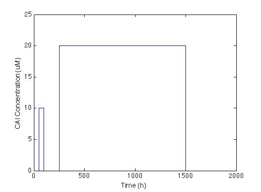
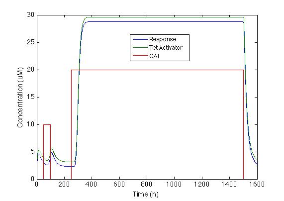
The first we did, was to establish the desired response. We want the system to react with a low and long lasting concentration of CAI. The Figure below shows the impulse we used to test the system: two pulses with different concentrations and different durations.
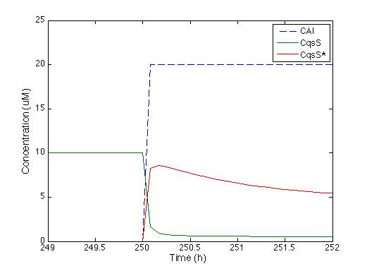
We knew that the equations of the CqsS protein behaviour are right because they were previously reported by Lelu et al (2012). So we needed to check that behaviour, the figure below shows the answer of CqsS with CAI.
It is easily seen that as soon as the CAI molecule is present the Cqss concentration is instantly decreased and also Cqss* (which stands for the CAI bound with the Cqss protein) just the way it’s supposed to.
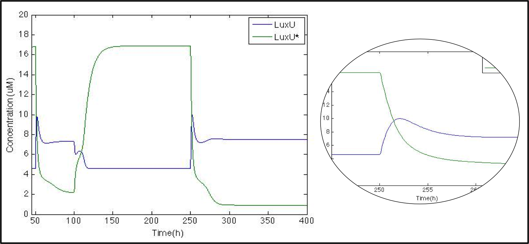
The next logical step is to check what happens with the luxU and its phosphorylated version now that we know that Cqss is modeled properly we might remove it as well as other molecules for visualization purposes.
In this case just for the sake of it we want to show you another way to do this we graphed here the ratio between LuxU and its phosphorylated version. Since we did not modify the pulse even though it is not shown we’ll maintain the x-axis scale to know when it comes. And just as expected whenever LuxU is greater than LuxU* the red line is below 1 and above 1 the other way around.
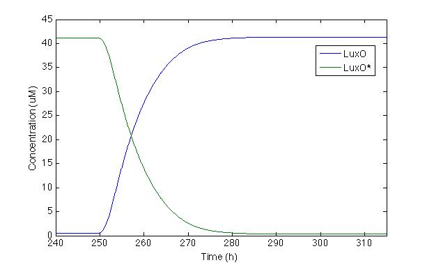
Now let’s check LuxO and its phosphorylated version, the same way we checked for Cqss and Cqss*, since LuxO and LuxU should behave fairly similar you get to see it in both displays.
We can actually see that the LuxO molecules are being dephosphorylated whenever there’s a pulse and the LuxO molecules remain constant inside a cell.
So far the model is working great but neither in the model nor in the actual lab any of these proteins matter to us (in the way that we can not easily measure them nor detect them), all we are interested in is the signal and this is what goes next, to prevent the chromoprotein from being expressed we used the pTet with its repressor under the Pqrr4 promoter, so the next logical step would be to evaluate the behavior of TetR and its dimer.
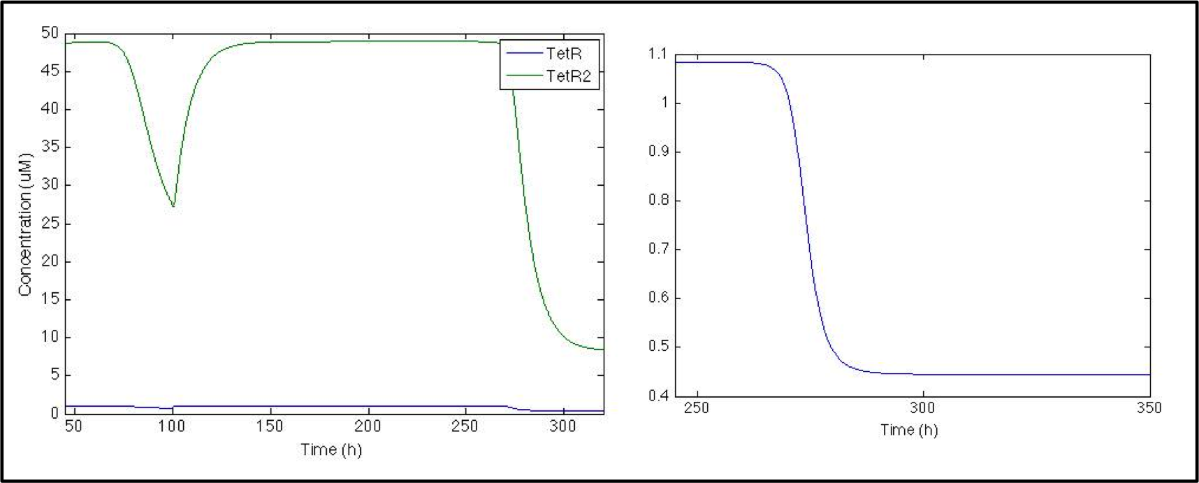
First thing we noticed as we looked at the plot is the difference in the concentration of TetR and TetRtetR but it makes sense since the dimerization rate is huge! Anyways the system should work as we want it to work, since when there is no pulse the actual repressor (TetRTetR) is all over the place, but as soon as the pulse is present there’s a dramatic decrease.
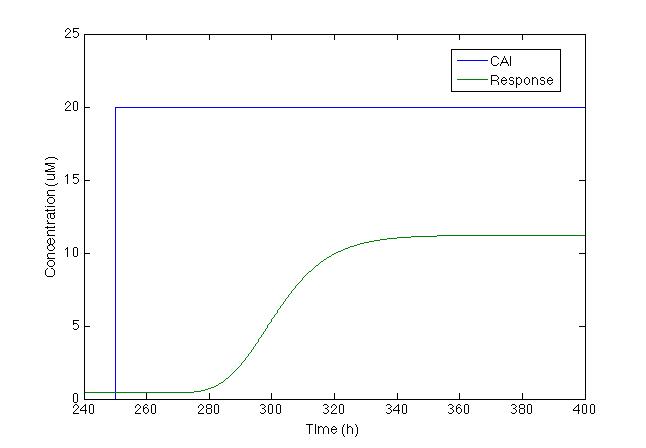
And now we should worry about the output, the actual signal that makes the sensor be useful to mankind, so since the chromoprotein is located downstream of pTet it should be repressed whenever there’s no pulse and vice versa.
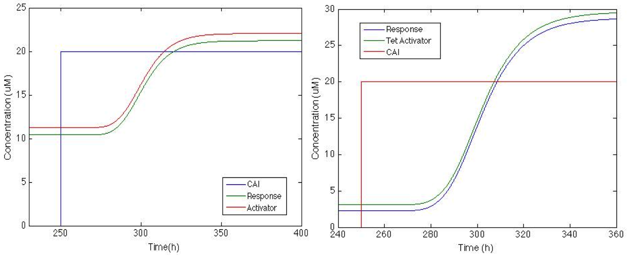
This is a really disappointing graph, but there’s plenty of tweaking we can do to increase the response, since it is obviously not going to be enough to be recognized. Luckily pTet also has an activator molecule TetA so we added it to the model as if it was also downstream of the pTet and not only should it increase the production of the chomoprotein but also itself
Now that we can see that the activator is actually being produced lets check how the response goes with this feedback.
And now the response is up, now this might be enough or it might not, there’s still much tweaking we can do to increase the response signal but if this is enough we can use this. When the part is ready at the lab we will know. "
"


